background image

EDS - TECHNICAL INSTRUCTIONS

EDS - TECHNICAL INSTRUCTIONS

EDS - TECHNICAL INSTRUCTIONS

EDS - TECHNICAL INSTRUCTIONS

EDS - TECHNICAL INSTRUCTIONS

12

• power supply : 230Vac - 12/24Vdc

• power consumption : 5W max

• current: 290 mA (365 mA with relays energized)

• terminals for standby battery 12/24Vdc

• optical path : 10-25m (25m standard)

• measuring ranges : 50-100-500-1000 mgr/m3 selectable

• LCD display

• microprocessor control system

• response time: 5-30 sec adjustable

• analog output: 0-5V

• analog output: 4-20mA

• RS485 digital output

• alarm relay output with adjustable threshold: 1A / 24Vdc

• clear relay output (maintenance request ): 1A / 24Vdc

• fault relay output: 1A / 24Vdc

• Laser pointer for optical collimation detector - reflector

• programming buttons

• dust protection tube: stainless steel (optional)

• detector box: self-extinguishing polycarbonate - class V0

- UL94 IEC695 - IEC707

• control panel box: plastic material - IP65

• detector protection index: IP50 (IEC 529-144)

• detector dimensions: 162x62x62 mm

• control panel dimensions: 190x180x110 mm

• power supply : 230Vac - 12/24Vdc

• power consumption : 5W max

• current: 320 mA (395 with relays energized)

• terminals for standby battery 12Vdc

• optical path : 10-25m (25m standard)

• measuring ranges : 50-100-500-1000 mgr/m3 selectable

• LCD display

• microprocessor control system

• response time: 5 - 30 sec adjustable

• analog output: 0,5-5V

• analog output: 4-20mA

• serial output: RS485

• alarm relay output with adjustable threshold: 1A / 24Vdc

• clear relay output (maintenance request ): 1A / 24Vdc

• fault relay output: 1A / 24Vdc

• Laser pointer for collimation optics TX-RX

• enclosure TX and RX: explosion  proof - II GD Ex d IIc T6 -

CESI - ATEX 092 - CE0722

• control panel box: plastic material - IP65

• control panel dimension: 190x180x110 mm

• TX and RX size: 145x125 mm

• RPV-TB - stainless steel dust protection tubes (optional)

TECHNICAL DATA - RPV20-EX

TECHNICAL DATA - RPV20-EX

TECHNICAL DATA - RPV20-EX

TECHNICAL DATA - RPV20-EX

TECHNICAL DATA - RPV20-EX

TECHNICAL DATA - RPV20

TECHNICAL DATA - RPV20

TECHNICAL DATA - RPV20

TECHNICAL DATA - RPV20

TECHNICAL DATA - RPV20

Summary of Contents for RPV20

Page 1: ...TALLATION SETUP AND INSTALLATION SETUP AND INSTALLATION SETUP AND INSTALLATION SETUP AND INSTALLATION SETUP AND MAINTENANCE MAINTENANCE MAINTENANCE MAINTENANCE MAINTENANCE EDS V Ca Nova Zampieri 6 37057 S G Lupatoto VERONA Tel 39045547529 Fax 390458750065 E mil eds eds eu Web www eds eu EDS V Ca Nova Zampieri 6 37057 S G Lupatoto VERONA Tel 39045547529 Fax 390458750065 E mil eds eds eu Web www eds...

Page 2: ...tallation 3 Installation 3 Installation 3 Installation 4 Control Panel 4 Control Panel 4 Control Panel 4 Control Panel 4 Control Panel 5 Menu Configuration 5 Menu Configuration 5 Menu Configuration 5 Menu Configuration 5 Menu Configuration 6 Configuration process 6 Configuration process 6 Configuration process 6 Configuration process 6 Configuration process 7 Led and Relays 7 Led and Relays 7 Led ...

Page 3: ...f the TX RX units and reflector on the walls to prevent them from falling to the ground 1 3 1 3 1 3 1 3 1 3 during installation care must also be taken in protecting the front window of the optical drive It is necessary to avoid scratching bumping deforming and dirtying this window which has the double function of mechanical protection and optical filter 1 4 before installation it is very importan...

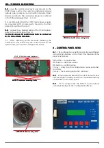
Page 4: ...nd connecting the control panel to the optical units you need to configure the device RPV20 Transceiver mounting holes RPV20 Transceiver mounting holes RPV20 Transceiver mounting holes RPV20 Transceiver mounting holes RPV20 Transceiver mounting holes V1 V2_V3 bolts for optical aligment RPV20EX TX RX mounting holes RPV20EX TX RX mounting holes RPV20EX TX RX mounting holes RPV20EX TX RX mounting hol...

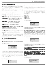
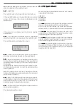
Page 5: ...l scale of the measurement This parameter is expressed in milligrams per cubic meter It is possible to choose between 4 possibilities 50mg m3 100mg m3 500mg m3 1000 mg m3 The display shows SET Scale 50 mg m3 To modify the parameter use the UP and DN keys and to confirm press the OK key 6 4 6 4 6 4 6 4 6 4 Now it is necessary to set the threshold beyond which the detector will give the alarm signal...

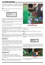
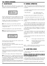
Page 6: ...6 7 6 7 At this point it is necessary to carry out the alignment of the optics alignment of the optical unit with the reflector model RPV 20 or aligment TX RX model RPV 20 EX Model RPV 20 Model RPV 20 Model RPV 20 Model RPV 20 Model RPV 20 Then go to the optical unit TX RX open the box cover and hold down the P2 button on the board for 2 seconds This turns on the Laser pointer the Laser can also b...

Page 7: ...6 17 At the end of the configuration phase RPV 20 starts normal operation The display shows the screen RPV20 R OK Dust 0mg m3 6 LEDS QAND RELAYS 6 LEDS QAND RELAYS 6 LEDS QAND RELAYS 6 LEDS QAND RELAYS 6 LEDS QAND RELAYS On the front of the switchboard there are also 4 LEDs respectively from above LINK LED ALARM LED CLEAR LED FAULT LED The LINK LINK LINK LINK LINK led white must flash and indicate...

Page 8: ... or lookdirectly be absolutely point the beam at the eyes or lookdirectly be absolutely point the beam at the eyes or lookdirectly be absolutely point the beam at the eyes or lookdirectly the beam by aligning itself with it the beam by aligning itself with it the beam by aligning itself with it the beam by aligning itself with it the beam by aligning itself with it During normal operation the Lase...

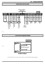
Page 9: ...INAL BOARD fig 1 fig 2 4 20mA OUTPUT CONNECTION EXAMPLE 4 20mA OUTPUT CONNECTION EXAMPLE 4 20mA OUTPUT CONNECTION EXAMPLE 4 20mA OUTPUT CONNECTION EXAMPLE 4 20mA OUTPUT CONNECTION EXAMPLE 4 20 mA output is of current source type No external voltage should be applied 220Vac 12Vdc RS485 ALARM RELAY CLEAR RELAY FAULT RELAY RS485 L G N A B AED BED SIG COM NC NO COM NC NO COM NC NO to optical detector ...

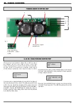
Page 10: ...he test menu keeping keys F1 and F2 pressed for 4 seconds IIn this menu it s possible to regulate 4mA and di 20mA values separately First value to adjust is 4mA The value can be regulated between 0 and 255 The higher is this value the lower is the current The default value for 4mA is 230 You can check the changing of the output current in realtime with a multimeter during regulation on terminalsAM...

Page 11: ...ANEL AND OPTICAL UNITS Cable between control panel and optical units should be shielded We suggest a shielded cable 4x1mm2 Shield should be connected to negative power supply on the control panel fig 4 optical detector RPV 20 EX TX B shielded cable 4x1mmq A B optical detector RPV 20 EX RX A B AED BED SIG COM NC NO COM NC NO COM NC NO to optical detector to external connection 0 5V analog output 4 ...

Page 12: ...n index IP50 IEC 529 144 detector dimensions 162x62x62 mm control panel dimensions 190x180x110 mm power supply 230Vac 12 24Vdc power consumption 5W max current 320 mA 395 with relays energized terminals for standby battery 12Vdc optical path 10 25m 25m standard measuring ranges 50 100 500 1000 mgr m3 selectable LCD display microprocessor control system response time 5 30 sec adjustable analog outp...

Page 13: ...e to the Purchaser with respect to the purchase In the event of any alleged breach of any warranty or any legal action brought by the purchaser based on alleged negligence or other tortuous conduct by EDS the Purchaser s sole and exclusive remedy will be repair or replacement of defective materials as stated above No dealer and no other agent or employee of EDS is authorized to modify extend or en...

Reviews: