EDS - TECHNICAL INSTRUCTIONS
EDS - TECHNICAL INSTRUCTIONS
EDS - TECHNICAL INSTRUCTIONS
EDS - TECHNICAL INSTRUCTIONS
EDS - TECHNICAL INSTRUCTIONS
6
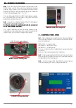
000000-------
OK = Stop
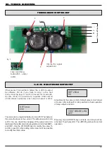
For optimal calibration, the blue LED of the optical unit
must remain on steady. To increase the signal, turn the
slightly the trimmer located at the bottom of the board
in a clockwise direction.
It will be seen that the flashing frequency will increase
as we turn the trimmer.
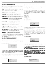
The value can vary between 1 - 240 minutes. By default
the time is set at 120 minutes. To modify the parameter
use the UP and DN keys and to confirm press the OK
key.
6.6
6.6
6.6
6.6
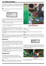
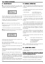
6.6 - Then the response time of the device must be set.
The display shows:
SET Delay
10 sec
The higher this time, the lower the sensitivity to rapid
changes in air opacity (but the measurement will be more
stable).
Similarly, the shorter this time, the greater the sensitivity
to rapid changes in air opacity.
You can set this value from a minimum of 5 seconds to
a maximum of 600 seconds.
The variation that can be set will vary in steps of 5
seconds up to the value of 60sec and the variation will
be in steps of 60 seconds. (5-10-15--20..60-120-180-
240 ... 600)
By default the time is set to 5 seconds. To modify the
parameter use the UP and DN keys and to confirm press
the OK key.
6.7
6.7
6.7
6.7
6.7 - At this point it is necessary to carry out the
alignment of the optics - alignment of the optical unit
with the reflector (model RPV-20) or aligment TX - RX
(model RPV-20-EX ).
Model RPV-20
Model RPV-20
Model RPV-20
Model RPV-20
Model RPV-20
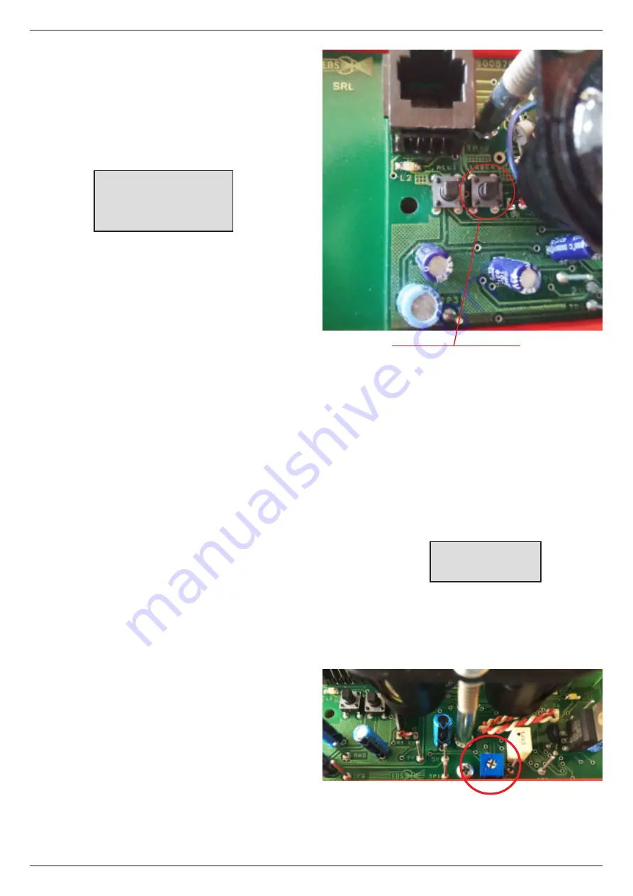
Then go to the optical unit (TX+RX) , open the box cover
and hold down the P2 button on the board for 2 seconds.
This turns on the Laser pointer (the Laser can also be
turned on by the switchboard by holding down the F2
key for 4 seconds).
Using a 5.5mm wrench, turn the V-V nuts (fig.3) to move
the optics so that the Laser beam illuminates the center
of the reflector. In this way the optical unit is collimated
with its reflector.
Once this is done, hold down the P2 button for 2 seconds
to switch off the Laser.
Model RPV-20-EX
Model RPV-20-EX
Model RPV-20-EX
Model RPV-20-EX
Model RPV-20-EX
For RPV20-EX, activate the Laser tool button
on the TX transmitter and direct the beam so that
is directed at the lens of the receiver. After this operation
turn off the laser
6.8
6.8
6.8
6.8
6.8 - Turn on the button of the laser instrument also
on the RX receiver and direct the beam so that it is
RPV20 Laser Tool button
directly on the lens of the transmitter. After this
operation
turn off the laser
6.9-
6.9-
6.9-
6.9-
6.9- With this procedure TX and RX are perfectly
aligned.
6.10
6.10
6.10
6.10
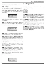
6.10 - At this point, observe the flashing of the blue
LED located on At the same time, the signal level is
displayed on the switchboard by means of a bar filled
with dots:


