2
EDS - TECHNICAL INFORMATION
SPARK DETECTOR
SCL-01
The SCL-01 is a spark detector suitable for the
detection of very fast sparks that can be
transported by pipelines of silos or warehouses
for the storage of flammable materials such as
sawdust, cotton yarn, cereal powders, metal
powders, etc. .
The possibility of detection in an extremely short
time of this detector can prevent the development
of a fire with serious consequences.
The SCL-01 detector is explosion proof ATEX
Ex-d. It must be installed according to the recent
legislation on the installation of electrical equipment
in potentially explosive atmospheres.
1
- INSTRUCTIONS
1.1
- The detector can be used as standalone or
(recommended) with the EV521 or SCU-04 control
panels expecially designed for this application. They
are equipped with internal stabilized power supply,
test circuits, timers and relay outputs. In addition,
these control panels are equipped with special
circuits so that the response time of the system
results to be very short.
1.2
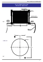
- Drill a hole of 130 mm (Fig. 7) diameter on
the surface of the pipe that must be surveilled.
1.3
- Install the equipment on the outer surface of
the pipe using the black O ring, the two fixing
brackets and the bolts supplied according to the
diagram shown in fig.6 and to the drill chart of fig.7.
The detector must “see” inside the pipe and
the
surveilled area has not to be subject to
variations of ambient light.
1.4
- We suggest not change the distance between
the front of the detector and the outer surface of
the pipe. The viewing window of the detector, must
not extend too far inside the pipe, because this
could create obstacles to the transport of the
materials flowing in the pipe or start an encrustation
that can obscure the vision window.
1.5
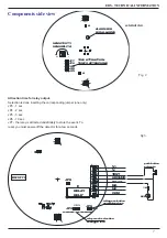
- Connect the equipment as shown in the
schematic diagram in fig. 3 or according the technical
instructions of control panel EV521 or SCP-04 if
present.
1.6
- The detector can be powered by AC or DC
voltage 12/24V. To obtain a greater immunity to
electrical noise power should always be supplied by
a stabilized power supply with backup battery.
If you choose the voltage of 24V DC or AC, remove
the selection jumper JP9 (Fig. 3).
1.7
- The detector is equipped with a relay output.
Terminals are available on the terminal board (terminals
1-2-3). The relay can be operated normally energized
or normally not energized. For the selection of
operating mode use the jumper JP2 :
1-2 position - relay normally energize
2-3 position - relay normally not energized
The indication of the terminals on the terminal board
is referred to the normally not energized relay
operation.
1.8
- The detector has the possibility to be tested
remotely. By connecting an external button (NO
contact) to terminal 6 (TEST) and terminal 5
(GROUND) a periodic test of the detector can be
performed. When the button is remotely pressed, a
real spark is passing through the pipe is simulated,
and so the detector reacts activating its output relay.


