3
EDS - TECHNICAL INFORMATION
1.9
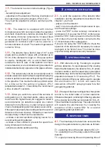
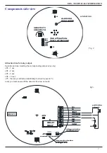
- The detector has two internal settings (Figure
2)
- sensitivity level adjustment
- adjustment of the duration of the time of activation of
the output relay (using the jumpers JP3-4-5-6-7)
They must be adjusted to achieve optimum perfor-
mance
1.10
- The detector is equipped with internal
microprocessor which not only provides the operation
and check of electronics, but also provides the check
of the status of internal components. In case of fault
an output signal (FAULT) is generated. Also +5V is
generated on terminal 4 and it can be used for a
remote indication of a fault. The maximum generated
current is 10mA.
1.11
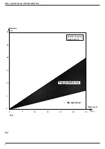
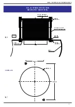
- The detector has a field of view of 90 ° (solid
angle) and is suitable for pipes with a diameter up to
50 cm. If the diameter is larger, or if the pipe section
is square, rectangular, etc.. to avoid dead zones
outside the field of view of the detector and have
ensure detection, we recommend using two detectors
installed diametrically opposite on the pipes surfaces.
1.12
- The output relay can be conveniently used to
actuate a solenoid valve that feeds a sprinkler spraying
nozzle to perform automatic extinguishing of the spark
in the pipeline. This nozzle therefore sprinkle water
for a time set by the setting of jumpers JP3-7
(adjustable between 0 - 10 seconds). We recommend
a time of about 5 seconds.
1.13
- When you want to be sure of the success of
extinguishing or in important plants, where security
must be at the highest level, we suggest to install a
second detector (or detectors couple) at a certain
distance from the first one, in order to have a second
check of extinguishing and if necessary a second try .
If the spark has already been extinguished the second
detector will remain inactive. Otherwise it react and
its output relay contact can be exploited to:
- activate a second sprinkler spraying nozzle for a
second extinguishing attempt
- activate a door shutter to prevent the spark from
being introduced into the silo
- activate a suitable audible warning
2
- OPERATION VERIFICATION
2.1
- to verify the operation of the detector after
installation and the adjustments described in the
chapter 1, you must:
- power on to the detector
- wait 1 minute to allow the microprocessor to ope-
rate the various settings
- press the TEST button remotely connected to
terminals 6-5. If you use the EV521 control panel,
press the TEST button present on the front of the
unit or press the remote button connected to the
17-18 terminals of the control panel.
If you are not using the TEST button to check the
operation of the detector it’s necessary to cause a
real spark in his field of view. This must be done
only after taking adequate security measures
3
- SYSTEM OPERATION
3.1
- With reference to fig. 5 relating to a system
with two detectors, if a spark passed in the viewing
field of the first detector, the detector SCL-01 enters
in alarm condition, and its output relay is energized
instantaneously and remains energized for an time
adjustable between 0-10 seconds (JP3-7). The
output contacts of this relay will be used to operate
the electrovalve VL1, which will cause the
intervention of the SS1 spraying nozzle for a first
extinguishing attempt.
3.2
- If the spark has been extinguished, the system
returns to the initial state of normal operation.
Otherwise the spark, continuing his flowing, will enter
in the viewing field of the second detector SCL-01.
This will activate its output relay. The output contacts
will operate the electrovalve VL2 causing the
activation of SS2 nozzle SS2 for a second
extinguishing attempt shutdown
4
- RESPONSE TIMES
4.1
- The time delay to be taken into account in the
design of a spark detection system are as follows:
T1 - operating time of the spark detector SCL-01
T2 - operating time of the relay output of the spark
detector
T3 - signal processing time and operating time of


