background image

SPM-010 Sump Pump Monitor and Control Unit 


EDSPN: 2052102004 

© Copyright 2022 Electronic Design Service, LLC All Rights Reserved 

Page 1 


Electronic Design Service


SPM-010 Sump Pump Monitor/Control Unit


User Guide


Summary of Contents for SPM-010

Page 1: ... 010 Sump Pump Monitor and Control Unit EDSPN 2052102004 Copyright 2022 Electronic Design Service LLC All Rights Reserved Page 1 Electronic Design Service SPM 010 Sump Pump Monitor Control Unit User Guide ...

Page 2: ...the revision history for the chapters in this User Guide Date Version Change Made April 24 2022 1 0 Original release Contact Us For the most up to date information about the Electronic Design Service products go to the Electronic Design Service website at www eldesignservice com Technical Support Phone 1 319 553 6080 Email support eldesignservice com www eldesignservice com ...

Page 3: ... 15 Resistive Sensor KUS SSS SPM 010 and SSR CU Installation 16 KUS SSS Resistive Sensor and SPM 010 Installation Instruction 18 SPM 010 Installation 19 Installation Warning 19 Operation 20 SPM 010 Dummy Cell Installation and Serial Number Location 20 SPM 010 Front Panel 21 SPM 010 iOS Application Installation and Operation 21 Installation 21 iOS Application Screenshot 24 Start and Operation Condi...

Page 4: ...iagram for Monitoring and Control Operation Mode 17 Figure 9 Resistive sensor SPM 010 and SSR CU Installation Diagram for Monitoring and Control Operation Mode with Redundant Pump 18 Figure 10 Silicon Cover 20 Figure 11 Dummy Cell Installation and Serial Number Location 20 Figure 12 SPM 010 Front Panel 21 Figure 13 Activation Message 22 Figure 14 Message Phone number at start 23 Figure 15 iOS Appl...

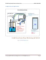
Page 5: ...itical conditions The advantages of SPM 010 are Independence from home WiFi and internet stability Indication of the actual water level power status and temperature at any given time Effective pump control Ability to operate in case of power outage SPM 010 unit monitors critical parameters of the home such as sump pump power loss sump True Water level with adjustable alarm level air temperature de...

Page 6: ...SPM 010 Sump Pump Monitor and Control Unit EDSPN 2052102004 Copyright 2022 Electronic Design Service LLC All Rights Reserved Page 6 Figure 1 Normal Operation Screen Example ...

Page 7: ...vel Sensor 240 33 Ohms 240 Ohms at empty 33 Ohms at full Resistive Sensor Level Transferring Characteristics KUS SSS 24 sensor two linear branches with break point at 21 3 length Resistive Sensor Resolution Range KUS SSS sensor 0 827 0 021m Resistive Sensor Input Two dry contacts Input Power 5VDC 500mA Battery 3 7V Lithium Ion 750mAH KLARUS LIR 14500 protected battery Internal Alarm 85dB Bluetooth...

Page 8: ...SPN 2052102004 Copyright 2022 Electronic Design Service LLC All Rights Reserved Page 8 Inside Box 1 SPM 010 device 2 WS 010 water level sensor 3 AA size Dummy Cell needs to be installed in SPM 010 in empty battery slot 4 120VAC 5VDC Power adapter ...

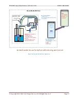
Page 9: ...me Parameters True Water Level Sump Pump Power and Operation Statuses Air Temperature Real Time Indication True Water Level Power and Operation Statuses Air Temperature ALARM ALARM Sound SPM 010 Sump Pump Monitor and Control Local Alarm Sound Rechargeable Battery Pump Control through SPM CU Optional Full System Monitoring with Bluetooth communication Wire Level Sensor Or KUS SSS SSL Sender Sensor ...

Page 10: ...vel Power and Operation Statuses Air Temperature ALARM ALARM Sound iPhone iPAD SMS Power Status Alarm Water LevelAlarm with truewater level parameter Air Temperature less than 45F SPM 010 BLE Battery included SUMP PUMP AREA AC Out SPM 010 Sump Pump Monitor and Control Local Alarm Sound Rechargeable Battery Pump Control through SPM CU Optional Full System Monitoring with Bluetooth communication Wir...

Page 11: ... SSS SSL sensor Notes 1 Resistive Sensor can be used for monitoring and control function 2 WS 010 sensor can be used for monitoring function only SPM 010 1 PUMP_CTRL 2 PUMP_3V3 3 V 4 V WS_SIG WS_GND 7 FLOAT_SWITCH Top View 5V_PWR V V Resistive Sensor 240 Ohms to 33 Ohms 120AC to 5VDC 0 5A Adapter 8 GND WS 010 Lw 1 85m 72 8 Lopw 0 95m 37 3 3VDC To SPM_CU Solid State Relay 3 3V 7mA KUS SSS SSL senso...

Page 12: ...n be attached to sump pump discharge pipe It allows to avoid WS 010 floating and blocking pump sensor See Figure 5 for this connection method The WS 010 is installed vertically on the PVC discharge pipe of the sump pump The sensor wire attaches to the PVC pipe with zip ties Place the sealed end of the sensor wire as far down the discharge pipe as possible Care must be taken to secure the sensor wi...

Page 13: ...r Monitoring Operation Mode WS 010 without SIP and SPM 010 Installation Instruction 1 Install WS 010 as shown on Figure 5 along of discharge pipe by using Cable Zip Ties Notes a Sealed end of WS 010 shall be 0 3 to 0 above bottom b Do not strongly cable tie the sensor wire around discharge pipe Sensor wire shall be loosely fixed to the pipe 2 Seal the sump cover area around of WS 010 installation ...

Page 14: ...mp cover This hole shall be far from sump pump switch and pump The sensor wire is installed inside of the SIP The SIP needs to be cut approximately 1 2 above the cover See Figure 6 installation diagram Bottom SPM 010 BLE AC Adapter WSU050 1500 R 5VDC PEX Pipe SIP Pipe Edge L 100 Ltop 2 3 51mm 76mm Lsump Sump Pump Sump Pump Switch Sump Pump Cover WS 010 Discharge Pipe Bundling Strap Switch Connecto...

Page 15: ...er installation area 3 Measure the Lsump see Figure 6 and keep record 4 Cut SIP bottom edge as shown on Figure 6 5 Cut SIP to adjust length approximately 1 to 2 above the cover level L_SIP Lsump Hcover 2 Where Hcover is thickness of cover 6 Install SIP into the mounting hole in the way when cut edge is connected to bottom of sump and seal the sump cover area of installation hole by using any plumb...

Page 16: ...ction diagram for SPM 010 connection Note The SSR CU unit or relay device with similar electrical characteristics needs to be used to implement pump control function The resistive sensor installation method is the same for all system installation variants The hole equal to sensor float diameter should be drilled in sump cover Sensor shall be installed far from sump pump switch and pump Bottom AC A...

Page 17: ...served Page 17 Bottom AC Adapter WSU050 1500 R KUS SSS Resistive Sensor L 100 Ltop 2 3 51mm 76mm Lsump Sump Pump Sump Pump Switch Sump Pump Cover Discharge Pipe Bundling Strap Sensor Float SPM 010 BLE 5VDC SSR CU Figure 8 Resistive sensor SPM 010 and SSR CU Installation Diagram for Monitoring and Control Operation Mode ...

Page 18: ...or and SPM 010 Installation Instruction 1 Measure the depth of sump Lsump Figure 7 and order sensor length a one step less or equal to Lsump value 2 Find the sensor location The location shall meet the following criteria c Be far enough from sump pump switch and pump d Be installed for deepest area 3 Measure external diameter Dext of sensor float and drill mounting hole hole diameter is Dext in th...

Page 19: ... Figure 6 and Figure 7 Velcro ONE WRAP Roll or similar can be used for SPM 010 mounting on discharge pipe Wire connections shall be performed in accordance with Figure 4 for sensor type which plan to be used Installation Warning Disconnect all sump pump circuit breakers before beginning work If you are unfamiliar or uncomfortable please contact a licensed electrician or plumber to perform the inst...

Page 20: ...on The SPM 010 is shipped with uninstalled Dummy Cell Serial Number is located on back side label see Figure 11 The Dummy Cell shall be installed before start of operation 1 Remove silicon cover see Figure 10 2 Open battery cover and install Dummy Cell see Figure 11 3 Close battery cover and install silicone cover Figure 10 Silicon Cover Figure 11 Dummy Cell Installation and Serial Number Location...

Page 21: ...ation of device Local sound alarm produces alarm sound in case of emergency water level situation Figure 12 SPM 010 Front Panel SPM 010 iOS Application Installation and Operation Installation Install SPM 010 Application on iPhone or iPAD from Apple store Before starting the application Enable background refresh for iPhone SPM 010 application Settings Sump Pump Monitor Background App Refresh Recomm...

Page 22: ...e added in Contact list First name field SPM 010 Last name Phone number The information shall follow the required format SPM 010 for First name field 1XXXXXXXXXX for phone number where message will be received If RMS is not needed there is no need to create special contact in Contact list During application start up the activation message will be sent to indicated phone number see Figure 13 and th...

Page 23: ...SPM 010 Sump Pump Monitor and Control Unit EDSPN 2052102004 Copyright 2022 Electronic Design Service LLC All Rights Reserved Page 23 Figure 14 Message Phone number at start ...

Page 24: ...on receives data steadily from device if RSSI is more than 90dBm The location of device shall guaranty that RSSI more than 90dBm for continuous operation It is important if outside monitoring configuration is used see Figure 3 But it is no problem if your smartphone or iPAD periodically losses communication with device due to out of receiving zone it will be automatically reconnected when smartpho...

Page 25: ...can operate independently from iOS device However if the remote monitor function is planned to be used the iOS device with installed SPM 010 application shall be used Start SPM 010 application on iOS smartphone or iOS tablet Note prepare iOS device if RMS is needed There are the following operation conditions 1 Normal operation see Figure 15 a Power is presented Battery is charged Status Indicator...

Page 26: ... real water level data is sent to phone number if it was assigned for RMS Water OK message will be sent if water level is below 5 water alarm threshold Figure 17 Water Level Alarm and Message Screenshots 4 Power Loss and Water Alarm This is combination of Power Loss and Water Alarm condition see Figure 18 for message Figure 18 Power Loss and Water Alarm message 5 Normal Operation with Battery char...

Page 27: ...enshot 6 Air temperature below 45 F see Figure 20 c Air temperature is indicated in Info row d Text message with Low Temperature text and real temperature data is sent to smartphone or iPAD number if it was assigned for RMS e When temperature reaches 4 F Temperature Norm text and real temperature data will be sent see Figure 20 Figure 20 Low Temperature and Temperature Normal Messages ...

Page 28: ...eral safety and high performance protection advancements The integrated reversed polarity protection plate shields battery from over charge over discharge high current and short circuit This feature also ensures that this battery can live up to its rating of 500 charge cycles Its steel shell and four tier safety protection also eliminate risk or short circuits from pressure or shock Never use devi...

Page 29: ...no cost to you to correct such defects in products found upon examination by EDS to be defective in materials or workmanship This warranty does not cover use of the product in improper installation and or improper maintenance of the product damage due to misuse owner s acts or omissions use outside the country in which the product was initially purchased This warranty does not cover pick up delive...

Page 30: ...ce Setting Bluetooth SumpPumpMonitorV010 Forget This Device and turn off and turn on power of SPM 010 device No Activation Message after device connection a Check spelling of iOS device Contacts setting see page 21 Water Level Graph and Value Not Indicated Properly a Restart power of SPM 010 if it is first start after calibration of WS 010 sensor Note KUS SSS sensor does not require calibration bu...

Reviews: