SPM-010 Sump Pump Monitor and Control Unit
EDSPN: 2052102004
© Copyright 2022 Electronic Design Service, LLC All Rights Reserved
Page 13
Bottom
AC Adapter
WSU050-1500-R
5VDC
L%
- 100%
Ltop = 2" - 3"
(51mm
–
76mm))
Ls
um
p
Sump Pump
Sump Pump
Switch
Sump Pump Cover
Cable Zip Ties
SPM-
010
BLE
Discharge Pipe
Bundling Strap
Switch
Connector
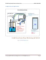
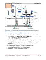
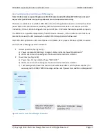
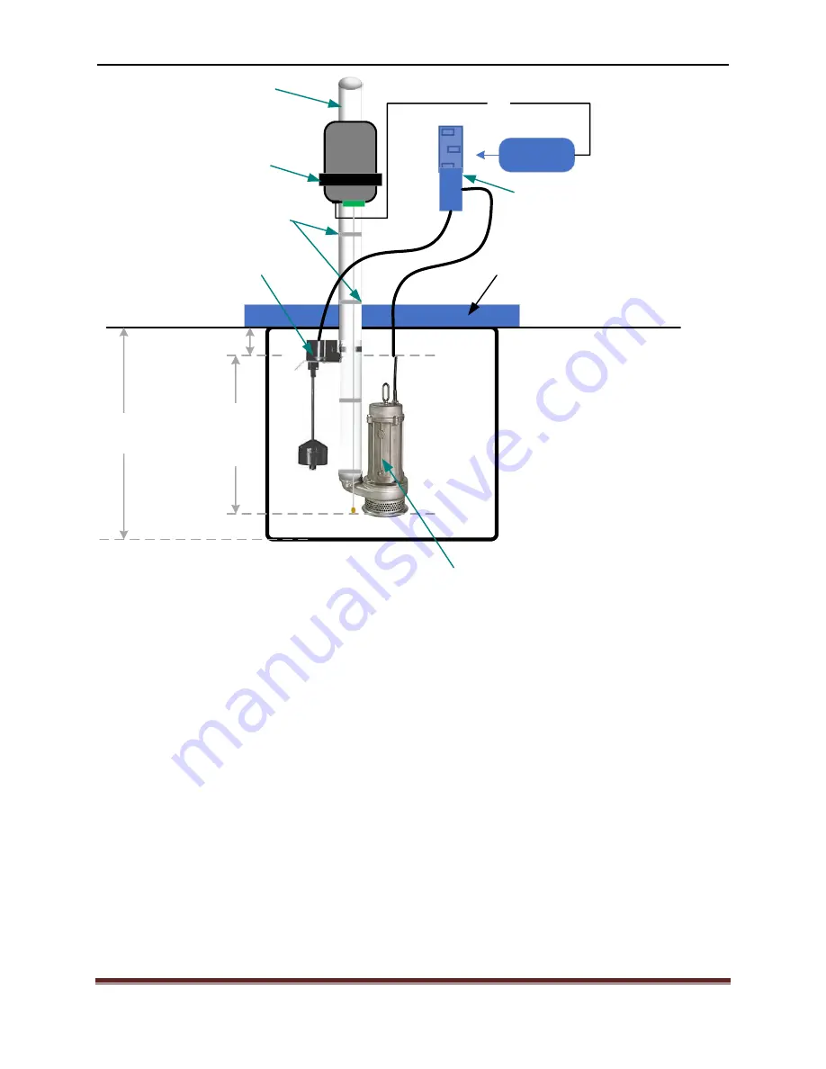
Figure 5 WS-010 Sensor (without Sensor Installation Pipe (SIP)) and SPM-010 Installation diagram for Monitoring Operation
Mode
WS-010 (without SIP) and SPM-010 Installation Instruction
1.
Install WS-010 as shown on Figure 5 along of discharge pipe by using Cable Zip Ties.
Notes:
a)
Sealed end of WS-010
shall be 0.3” to 0. ” above bottom
b)
Do not strongly cable tie the sensor wire around discharge pipe. Sensor wire shall be
loosely fixed to the pipe.
2.
Seal the sump cover area around of WS-010 installation by using any plumbing caulk. if it is
needed.
3.
Install SPM-010 in accordance with SPM-010 Installation section.
4.
Connect system in accordance with Figure 5 and Figure 4.
NOTE: DO NOT CUT OR INCREASE WIRE SENSOR LENGTH!!!!!


