RCX C-Link Series
Connecting the Extender Assembly
EDT, Inc.
2011 June 29
6
synchronizing signals to ensure that the starting pixel of each raster lines up across the X, Y and Z channels.
The resync cable also supplies power to the extenders.
CAUTION
To avoid damaging your components, you should verify that the entire system is connected properly
before you apply power to any component. In particular, do not apply power to the resync cable while
you are connecting it to, or disconnecting it from, an extender.
With a standard framegrabber
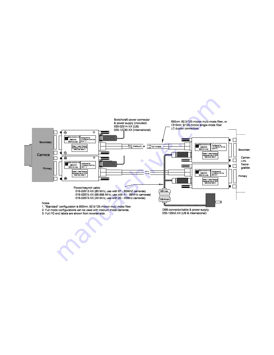
For medium- or full-mode operation with a standard framegrabber, you will need four extenders: two at the
camera end, and two at the framegrabber end (see
Figure 5
).
NOTE
Each extender unit is physically different from the others, so you cannot simply change the configuration
codes and use the units interchangeably.
Figure 5. Full mode: multiple ext standard framegrabber
To set up this system:
1.
Install your Camera Link framegrabber and software as instructed by its manufacturer.
2.
Verify extenders are configured properly (see
Configuration and LED Configuration Codes on page 7
).
3.
Turn off power to all devices.
4.
Connect the extender labeled
X Channel Camera
to the camera's primary MDR26 connector.
5.
Connect the extender labeled
YZ Channel Camera
to the camera’s secondary MDR26 connector.
6.
Connect the extender labeled
X Channel FG
to the framegrabber’s primary MDR26 connector.
7.
Connect the extender labeled
YZ Channel FG
to the framegrabber’s secondary MDR26 connector.
8.
Connect the two power supplies with coaxial power connectors to the two camera-end extenders.
9.
Verify that you have the correct resync cable for your camera (see
Figure 5
) and connect the cable to
both extenders at the framegrabber end. The two ends of the resync cable are interchangeable.
10. Connect the power supply with the 9-pin D-shell connector to the resync cable connector.


