RCX C-Link User’s Guide
LED Status
EDT, Inc. November 2006
8
LED Status
•
When first powered on, the LED displays the current blink code, then blinks erratically for a few
seconds while the firmware is loading.
•
In normal operation, a solid green light indicates the RCX C-Link is working properly.
•
Slow blinking indicates the RCX C-Link is not receiving a correct fiber optic signal.
•
Rapid blinking indicates the RCX C-Link is not locked into the camera clock.
•
If the RCX C-Link displays a combination of slow and rapid blinks, both errors are present.
NOTE
When used as an extension cord, the RCX C-Link on the frame-grabber end generates its own
camera clock; therefore, a rapid blink indicates a hardware fault in the RCX C-Link, or, in a full- or
medium-mode system, possibly the resync cable.
A slow blink indicates a problem with the fiber optic connection
from
the remote device
to
the device
with the slowly blinking LED. Common causes are:
•
no power at the transmitting end;
•
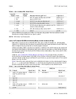
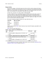
blink codes with incompatible link rates (see
Table 1
);
•
a broken fiber or an incorrect fiber type; or
•
dust or dirt in the fiber optic transceivers (see
Fiber Optic Transceivers on page 15
).
Configuration
The standard firmware for the RCX C-Link supports most Camera Link base-mode cameras from 20
to 80 MHz, UART data rates of up to 19.2 KBaud. (Higher baud rates are possible.) By setting the
operating mode using the LED’s blink code, you can configure the RCX C-Link to support many
different kinds of cameras for use with a PCI DV-FOX fiber-optic frame-grabber, or for use at either
end of an extension cord.
Each RCX C-Link leaves EDT configured with the appropriate blink code to support its required
operation. For a typical base-mode system,a blink code of 1-1 at the camera end and 2-1 at the frame-
grabber end permits standard base-mode operation at clock frequencies of 20–40 MHz. For a typical
full mode system, a blink code of 1-4 on both RCX C-Links at the camera end, and of 2-4 on both at
the frame-grabber end, permits standard full-mode operation at clock frequencies of 60–80 MHz.
Each RCX C-Link leaves EDT labeled with that blink code with which it has been configured. On such
labels for medium- or full-mode systems,
X Channel
refers to the primary MDR-26 connnector on the
camera or frame-grabber, and
YZ Channel
to the secondary.
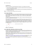
Operating Modes and Blink Codes
The RCX C-Link can transfer camera data at various speeds, depending on the operating mode
chosen. You select an operating mode by setting a pattern of blinks — the blink code — for the
module’s LED.
A blink code consists of two digits: for those blink codes that begin with 1 or 2, the first indicates
whether the module is at the camera end (a blink code first digit of 1) or the frame-grabber end (a blink
code first digit of 2). The second digit of the blink code must be the same for both camera and frame-
grabber ends.


