
RCX C-Link User’s Guide
Options
EDT, Inc. November 2006
18
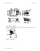
Resync Cable
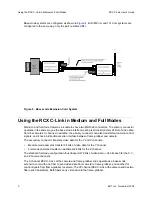
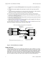
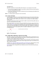
When used for medium- and full-mode extension cords, two RCX C-Links are needed at the frame-
grabber end. The EDT resync cable sends a common clock signal from an oscillator inside the DB-9
shell to each of the two RCX C-Links at the frame-grabber end. This cable also allows the X Channel
RCX C-Link to signal the YZ channel RCX C-Link when to start each raster.
The two Lemo connectors on the resync cable are interchangeable.
The resync cable must have an oscillator frequency greater than or equal to the camera pixel clock
rate. The pixel clock re-created for the frame-grabber is asynchronous to that generated by the
camera; thus, the amount of time spent in horizontal blanking varies from one raster line to the next.
If the camera's clock rate is slower than that of the resync cable, a greater percentage of time will be
spent in horizontal blanking at the frame-grabber.
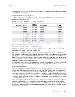
Three resync cables are available, offering 40, 60, and 80 MHz clock rates:
Clock Rate
EDT Part Number
40 MHz
016-02673-00
66.666 MHz
016-02675-00
80 MHz
016-02613-00
Choose a blink code from
Table 1
whose frequency range includes the frequency generated by the
cable assembly.
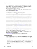
Table 8
shows the signal assignments:
If you’re using the resync cable, you will also need a power source, such as the
International Power
Supply With DB-9 Connector
described on
page 19
.
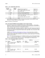
Table 8. Resync Cable Pinout With Male DB-9
Lemo
Pin
Lemo Signal
DB-9 Signal
DB-9
Pin
1 START, LVDS signal from X to YZ RCX C-Link
— unconnected —
2 power
power
9
3
CLOCK+, LVDS pixel clock into X and YZ RCX C-Links
— unconnected —
4 CLOCK-, LVDS pixel clock into X and YZ RCX C-Links
— unconnected —
5 reserved
— unconnected —
6 START_RASTER-, LVDS signal from X to YZ RCX C-Link
— unconnected —
7 ground
ground
5


