RCX C-Link User’s Guide
Using the RCX C-Link in Base Mode
EDT, Inc. November 2006
2
The
RCX C-Link data sheet
lists the product specifications.
Supported Cameras
The RCX C-Link supports base- and medium-mode Camera Link cameras when used with the
PCI DV FOX frame-grabber within the 200 MB per second bandwidth limitation of the PCI DV FOX
DMA engine. The RCX C-Link supports base-, medium-, and full-mode cameras from 20–80 MHz in
extension cord mode, using third-party frame-grabbers.
Medium- and full-mode extension cord operation requires the use of special versions of the RCX
C-Link.
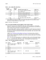
RCX C-Link modules leave EDT configured for the operating mode specified when they were ordered.
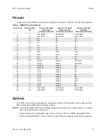
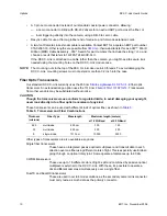
Available operating modes are listed in
Table 1
on
page 9
; instructions for reconfiguring the RCX
C-Link are in
Setting the Blink Code on page 10
.
References
The following related publication contains additional information on the EDT PCI digital video driver
and the PCI DV FOX frame grabber, including information on acquiring images:
Manual
URL
PCI Digital Video User’s Guide
www.edt.com/manuals/PDV/pcidv.pdf
Using the RCX C-Link in Base Mode
The RCX C-Link in base mode has one MDR-26 connector. Each pixel clock transfers 24 bits of video
data from the camera’s X channel. In addition, the RCX C-Link can also transfer four camera control
signals, and it has a bidirectional serial interface between frame-grabber and camera.
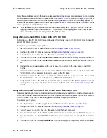
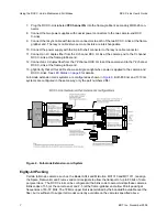
You can configure a system using the PCI DV FOX as a frame-grabber, or you can use two RCX
C-Link modules to form a fiber optic extension cord, with one module at the camera and the other at
the frame-grabber. Both uses are described below.
Using a Base-mode RCX C-Link With a PCI DV FOX
To configure the RCX C-Link for use with the PCI DV FOX frame-grabber:
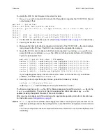
1. Install the software driver as instructed in the
PCI Digital Video User’s Guide
.
2. Configure the RCX C-Link as described in the
Setting the Blink Code on page 10
.
3. Turn off power to the RCX C-Link, the camera, and the host computer.
4. Install the PCI DV FOX frame-grabber into a host PCI slot as described in the host computer doc-
umentation.
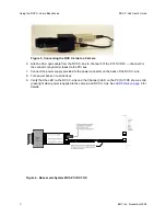
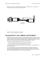
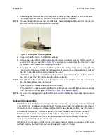
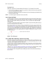
5. Connect the RCX C-Link directly to the MDR-26 connector on the back of the camera, as shown
in Figure 3.


