background image

RCX C-Link User’s Guide

Using the RCX C-Link in Base Mode

EDT, Inc.  November 2006

4

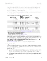
Using a Base-mode RCX C-Link As an Extension Cord

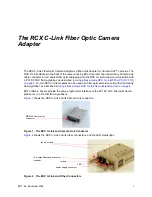
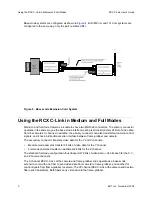
You can use two RCX C-Link modules to form a fiber optic extension cord, with one module at the 
camera and the other at the frame-grabber. In this case, the pixel clock rate into the frame-grabber 
can be significantly higher than that presented by the camera, and the amount of time spent in blanking 
will vary from line to line and frame to frame. 

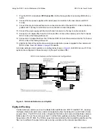
To use two RCX C-Link modules as an extension cord:

1. Install your Camera Link frame grabber and software as instructed by its manufacturer.

2. Configure both RCX C-Link modules as described in 

Setting the Blink Code on page 10

. One RCX 

C-Link is for the camera end, and the other is for the frame-grabber end.

3. Ensure that power is off to all devices.

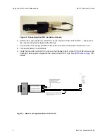
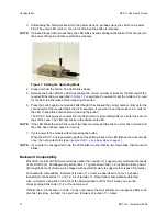
4. Connect the RCX C-Link labeled 

Camera End 

to the MDR-26 connector on the back of the cam-

era.

5. Connect the RCX C-Link labeled 

For


Frame Grabber 

to the MDR-26 connector on the back of 

the frame-grabber.

6. Attach a fiber optic cable from one RCX C-Link to the other.

7. Connect the power supplies provided to the power connector on the back of each RCX C-Link 

module.

8. Turn power back on to all devices.

9. Verify that both LEDs show a solid green light when power is applied to the camera and RCX 

C-Links. See 

LED Status on page 8

 for details.

Frame-grabber and camera operation is the same as when using a standard Camera Link cable.

Summary of Contents for RCX C-Link

Page 1: ...RCX C Link Fiber Optic Camera Adapter for use with Camera Link cameras November 20 2006 008 02368 03 ...

Page 2: ...ncidental damages the above limitations may not apply to you EDT s liability to you for actual damages for any cause whatsoever and regardless of the form of the action whether in contract tort including negligence product liability or otherwise will be limited to 50 fifty U S dollars No part of this manual may be reproduced or transmitted in any form or by any means electronic or mechanical witho...

Page 3: ... mode RCX C Link As an Extension Cord 6 Eighty bit Packing 7 LED Status 8 Configuration 8 Operating Modes and Blink Codes 8 Blink Codes for Base mode Systems 9 Blink Codes for Medium and Full mode Systems 10 Setting the Blink Code 10 Backward Compatibility 11 Firmware 12 Verifying the Firmware 12 Updating the Firmware 12 Pinouts 14 Options 14 Fiber Optic Transceivers 15 Transceiver Care 16 Lemo Co...

Page 4: ...RCX C Link User s Guide EDT Inc November 2006 iv ...

Page 5: ...r two RCX C Link modules can be used as a fiber optic extension cord with a third party frame grabber as described in Using a Base mode RCX C Link As an Extension Cord on page 4 EDT software drivers provide the same programmer interface to the PCI DV FOX fiber optic frame grabber as to our other frame grabbers Figure 1 shows the RCX C Link and its Camera Link connector Figure 1 The RCX C Link and ...

Page 6: ...ng images Manual URL PCI Digital Video User s Guide www edt com manuals PDV pcidv pdf Using the RCX C Link in Base Mode The RCX C Link in base mode has one MDR 26 connector Each pixel clock transfers 24 bits of video data from the camera s X channel In addition the RCX C Link can also transfer four camera control signals and it has a bidirectional serial interface between frame grabber and camera ...

Page 7: ...el 0 is the connector physically closest to the PCI bus 7 Connect the power supply provided to the power connector on the back of the RCX C Link 8 Turn power back on to all devices 9 Verify that the LED on the RCX C Link and the Channel 0 LED on the PCI DV FOX show a solid green light when power is applied to the camera and RCX C Link See LED Status on page 8 for details Figure 4 Base mode System ...

Page 8: ...re both RCX C Link modules as described in Setting the Blink Code on page 10 One RCX C Link is for the camera end and the other is for the frame grabber end 3 Ensure that power is off to all devices 4 Connect the RCX C Link labeled Camera End to the MDR 26 connector on the back of the cam era 5 Connect the RCX C Link labeled For Frame Grabber to the MDR 26 connector on the back of the frame grabbe...

Page 9: ...ransfer four camera control signals and it has a bidirectional serial interface between frame grabber and camera The secondary connector transfers video data for the Y and Z channels Medium mode cameras transfer 24 bits of video data for the Y channel Full mode cameras transfer an additional 24 bits for the Z channel The standard full mode configuration thus transports 72 bits of video data 24 bit...

Page 10: ...annel Camera into the camera s secondary MDR 26 connec tor 6 Connect the two power supplies with coaxial power connectors to the two camera end RCX C Links 7 Connect an LC duplex fiber from the X channel RCX C Link at the camera end to channel 0 of the PCI DV FOX the connector physically closest to the PCI Bus 8 Connect an LC duplex fiber from the YZ channel RCX C Link at the camera end to channel...

Page 11: ... C Link at the frame grabber end 13 g3g3Verify that all four LEDs show a solid green light when power is applied to the camera and RCX C Links See LED Status on page 8 for details Full mode extension cords systems are configured as shown in Figure 6 Both 850 nm and 1310 nm systems are configured in the same way only the part numbers differ Figure 6 Full mode Extension cord System Eighty bit Packin...

Page 12: ...re possible By setting the operating mode using the LED s blink code you can configure the RCX C Link to support many different kinds of cameras for use with a PCI DV FOX fiber optic frame grabber or for use at either end of an extension cord Each RCX C Link leaves EDT configured with the appropriate blink code to support its required operation For a typical base mode system a blink code of 1 1 at...

Page 13: ...best served by blink codes 1 3 and 2 3 If the camera needs only 16 data bits or fewer transferred per clock cycle instead of all 24 it is possible to use blink codes 1 2 and 2 2 instead and thus operate the link at 1 25 GBaud for longer range and lower power dissipation The selection of 16 bit mode is made only at the frame grabber end through blink code 2 2 or through the mode16 1 directive in a ...

Page 14: ...RCX C Link modules leave EDT configured with the blink code that s correct for the operating mode specified when they were ordered To set the blink code 1 Turn off power to the RCX C Link module Only a power supply need be connected to it nothing else It may be helpful however to connect the power supplyto a power strip or otherwise arrange matters so that you can easily turn the power back on whi...

Page 15: ... in the pattern selected NOTE If the LED blinks the error blink code of two fast two slow and two fast an error has occurred and the code has not been saved to memory 7 Cycle power to the module without pressing the button When the RCX C Link is powered up without the button pressed the LED flashes the current code once then show its status see Using the RCX C Link in Base Mode on page 2 NOTE If y...

Page 16: ...he RCX C Link module bit by bit with the firmware in the specified firmware file If they are the same it reports verified and 0 errors if not it reports not verified and lists the errors NOTE Avoid updating the firmware unless it s necessary If your RCX C Link module is working correctly there s ordinarily no need to update its firmware Updating the Firmware The instructions below allow you to upd...

Page 17: ...ector 1 38000 rgb11cm80_a01 ncd 2vp2fg256 2006 03 30 20 12 36 sector 2 60000 rgb11fg40_a01 ncd 2vp2fg256 2006 03 30 19 57 41 sector 3 88000 rgb11fg60_a01 ncd 2vp2fg256 2006 03 30 20 02 08 sector 4 b0000 rgb11fg80_a01 ncd 2vp2fg256 2006 03 30 20 09 30 sector 5 d8000 fud02b ncd 2vp2fg256 2006 03 28 15 59 19 If your output appears faulty check the blink code cables and connections If you still have p...

Page 18: ... cameras Table 4 MDR 26 Pin Assignments Camera end Frame grabber end Camera Link signal base mode primary connector Camera Link signal medium mode secondary connector Camera Link signal full mode secondary connector 1 1 inner shield inner shield inner shield 14 14 inner shield inner shield inner shield 2 25 X0 Y0 Y0 15 12 X0 Y0 Y0 3 24 X1 Y1 Y1 16 11 X1 Y1 Y1 4 23 X2 Y2 Y2 17 10 X2 Y2 Y2 5 22 Xclk...

Page 19: ...ransceiver An extended range option uses the 1310 nm Finisar FTRJ11319F1GTL Transceivers from other vendors may be substituted without notice CAUTION Though the transceivers we use conform to regulated limits to avoid damaging your eyesight never look directly into a fiber optic transceiver of any kind These transceivers can be used with different kinds of optical fiber as shown in Table 5 Other t...

Page 20: ... 8 using Lemo pin numbering Pin 2 is always power to the RCX C Link 4 75 to 18 V DC Pin 7 is always ground for both signals and power The other five pins are defined by the firmware installed on the RCX C Link These pins are normally used at CMOS 3 3 V signal levels though the RCX C Link can be configured with minor hardware modifications to use pins 1 6 and 3 4 as LVDS signal pairs Figure 8 Lemo ...

Page 21: ...th 24 inches long are left loose for you to hook up your own power source The required power is 4 75 to 18 V DC Table 7 shows the color coding for the Lemo to DB 9 RS 232 cable and how the standard firmware in rgb11 rcx uses each wire DB 9 pins 1 4 and 6 are wired together and unconnected 7 and 8 are also wired together and 9 is also unconnected these signals are not otherwise used Table 6 Lemo to...

Page 22: ...amera s clock rate is slower than that of the resync cable a greater percentage of time will be spent in horizontal blanking at the frame grabber Three resync cables are available offering 40 60 and 80 MHz clock rates Clock Rate EDT Part Number 40 MHz 016 02673 00 66 666 MHz 016 02675 00 80 MHz 016 02613 00 Choose a blink code from Table 1 whose frequency range includes the frequency generated by ...

Page 23: ...aft connectors The two RCX C Links at the frame grabber end of a full mode system receive power from our resync cable through a female DB 9 connector The resync cable connects to the RCX C Links through two Lemo 7 pin connectors Dimensions The RCX C Link box has the dimensions shown in Figure 9 NOTE With respect to the dimensions shown in Figure 9 Connector dimensions are approximate refer to manu...

Page 24: ...Dimensions EDT Inc November 2006 20 Figure 9 RCX C Link Dimensions Figure 10 shows the cable clearance Cable clearance for optical fiber can vary depending on the fiber used the value shown is typical Figure 10 Cable Clearance ...

Reviews: