Using the RCX C-Link in Medium and Full Modes
RCX C-Link User’s Guide
5
EDT, Inc. November 2006
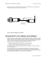
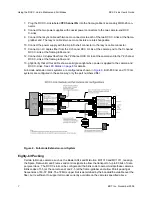
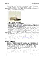
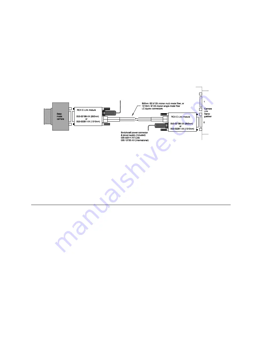
Base-mode systems are configured as shown in
Figure 4
. Both 850 nm and 1310 nm systems are
configured in the same way; only the part numbers differ.
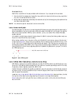
Figure 5. Base-mode Extension Cord System
Using the RCX C-Link in Medium and Full Modes
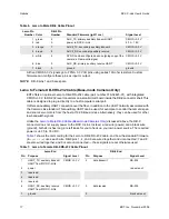
Medium- and full-mode Camera Link cameras have two MDR-26 connectors. The
primary connector
operates in the same way as the base-mode interface; each pixel clock transfers 24 bits of video data
from the camera’s X channel. In addition, the primary connector can also transfer four camera control
signals, and it has a bidirectional serial interface between frame-grabber and camera.
The
secondary connector
transfers video data for the Y and Z channels:
•
Medium-mode cameras transfer 24 bits of video data for the Y channel.
•
Full-mode cameras transfer an additional 24 bits for the Z channel.
The standard full-mode configuration thus transports 72 bits of video data — 24 bits each for the X, Y,
and Z camera channels.
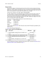
The X channel RCX C-Links at the camera and frame-grabber ends operate as a base-mode
extension cord, with one fiber to send video data from camera to frame-grabber, and another for
control signals from frame-grabber to camera. The YZ channel RCX C-Link at the camera end has two
fiber optic transmitters. Both fibers carry video data to the frame-grabber.


