background image

AVERY BASE UNIT - USE + CARE GUIDE

15

Where to install the Avery Base Unit

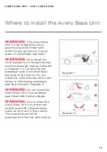
WARNING: 

This Avery Base 

Unit is only suitable for use in 
approved vehicles fitted with 
ISOFIX lower anchors or 3 point 
static or retractable seat belts.

WARNING: 

Only install the 

child restraint on a forward-facing 
vehicle passenger seat as indicated 
in Diagram 1. A forward-facing 
passenger seat is one that faces 
the front of the vehicle. Do not 
install the child restraint into a rear-
facing or side-facing passenger 
seat as pictured in Diagram 2.

WARNING: 

Do not install the 

Avery Base Unit in a passenger 
seat fitted with frontal airbags.

WARNING:

 Do not install the 

Avery Base Unit in a centre rear 
vehicle seat with a transmission 
hump on the floor of the vehicle. 
The support leg must be 
positioned on the flat vehicle floor.

Diagram 1.

Diagram 2.

Summary of Contents for Avery Base Unit

Page 1: ...Avery Base Unit FA0062 Use Care Guide ...

Page 2: ...Certified to European ECE R44 04 in Group 0 as approved by Waka Kotahi NZTA IMPORTANT Keep these instructions for future reference Always follow the manufacturer s instructions Read all instructions carefully before assembly and use of this Avery Base Unit The correct use and maintenance of this product is essential ...

Page 3: ... it is very important that you read this instruction manual carefully In particular pay attention to the warnings included as well as the correct installation methods provided Subtle differences can make a huge difference when it comes to safety We believe in long lasting relationships with our customers and we d love you to keep in touch You can sign up to our newsletter via our website or follow...

Page 4: ... Installing the Avery Base Unit 14 Where to install the Avery Base Unit 15 Important installation information 16 Installing the Avery Base Unit with the vehicle belt 17 Installing the Avery Base Unit with the ISOFIX system 23 Using the Avery Capsule with the Avery Base Unit 29 Safety checklist 31 How to care for and maintain your Avery Base Unit 32 Determining the base unit s expiry date 34 WARRAN...

Page 5: ...capsule manual for all fitting criteria Never leave your child unattended NEVER leave your child unattended in the child restraint Position in vehicle Never use this child restraint base in a vehicle passenger seat fitted with airbags Only fit on a forward facing vehicle passenger seat Never fit into a rear facing or side facing vehicle seat The rear vehicle seat is safest Vehicle compatibility Th...

Page 6: ...psule compatibility This child restraint base is only compatible with Edwards Co capsule models FA0050 FA0053 and FA0062 NEVER use this product with another capsule shell Correct use of the base unit NEVER use this product without installing it securely into your vehicle NEVER alter or modify this product in any way This can affect its performance in the event of a collision DISCARD this product i...

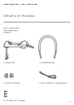
Page 7: ...AVERY BASE UNIT USE CARE GUIDE 7 What s in the box Use Care Guide this instruction manual 1 x Base Unit 1 x Stabilising Bar 3 x Screws inc 1 spare 2 x ISOFIX Guides 1 x Vehicle Belt Locking Device ...

Page 8: ...AVERY BASE UNIT USE CARE GUIDE 8 Avery Base Unit components Stabilising Bar Vehicle Belt Locking Device ISOFIX Connectors Support Leg Support Leg Adjuster Button Capsule Release Lever Vehicle Belt Guide ...

Page 9: ...AVERY BASE UNIT USE CARE GUIDE 9 Preparing the Avery Base Unit ...

Page 10: ...he holes at the rear of the base unit Important Press the ends of the stabilising bar down firmly until they reach the base of the holes 2 Turn the base unit on its side and insert the two screws into the corresponding holes on the underside of the base unit 3 Using a Phillips screwdriver fasten the screws until the stabilising bar is secure and cannot be removed 4 Pull upwards on the stabilising ...

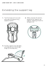
Page 11: ... button lengthen the support leg slightly releasing it from its storage lock 3 Pull the support leg upwards and extend so it is at a right angle to the base unit Illustrate the left side then duplicate and reflect to create the right Make sure buttons labels etc are present where they are shown in photo Replicate previous illustration and extend leg 90 ...

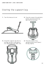
Page 12: ...the underside of the base unit 4 Press the support leg adjustor button and extend the leg slightly Illustrate the left side then duplicate and reflect to create the right Make sure buttons labels etc are present where they are shown in photo Illustrate the left side then duplicate and reflect to create the right Make sure buttons labels etc are present where they are shown in photo Replicate previ...

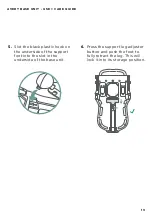
Page 13: ...e slot in the underside of the base unit 6 Press the support leg adjuster button and push the foot to fully retract the leg This will lock it into its storage position Illustrate the left side then duplicat and reflect to create the right Make sure buttons labels etc are present where they are shown in photo ...

Page 14: ...AVERY BASE UNIT USE CARE GUIDE 14 Installing the Avery Base Unit ...

Page 15: ... as indicated in Diagram 1 A forward facing passenger seat is one that faces the front of the vehicle Do not install the child restraint into a rear facing or side facing passenger seat as pictured in Diagram 2 WARNING Do not install the Avery Base Unit in a passenger seat fitted with frontal airbags WARNING Do not install the Avery Base Unit in a centre rear vehicle seat with a transmission hump ...

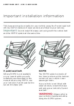
Page 16: ...me time ISOFIX The ISOFIX system consists of two lower anchors at the bottom corners of your vehicle s rear passenger seats If you vehicle is not fitted with lower anchors install this base unit using your vehicle s 3 point seat belt WARNING Always refer to your vehicle s handbook before using the ISOFIX system 3 point seat belt Where ISOFIX is not available or you cannot achieve a safe installati...

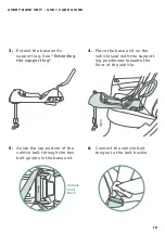
Page 17: ...before starting the installation pull your vehicle belt out to its full extent and at the point where it retracts into your vehicle wall fold the vehicle belt over and clip it with a clothes peg This will stop the belt retracting while you are installing the base unit Remove the peg when the installation is complete 2 Loop the vehicle belt locking device onto the stabilising bar ...

Page 18: ...unit 6 Connect the vehicle belt tongue to the belt buckle 3 Extend the base unit s support leg See Extending the support leg 4 Place the base unit on the vehicle seat with the support leg positioned towards the floor of the vehicle Extend illustration even though the photo reference isn t wide enough Vehicle Seat Back ...

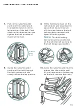
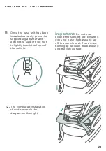
Page 19: ... sash shoulder portion of the vehicle belt to establish tension on the lap portion of the belt Push down on the base unit as you tighten the belt to achieve maximum tension 8 While holding tension on the vehicle belt and ensuring the lap portion doesn t loosen off close and secure the belt locking device across both layers of belt together Note The belt locking device should be positioned on the v...

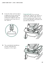
Page 20: ...he base unit has been installed securely press the support leg adjuster and extend the support leg foot to lightly touch the floor of the vehicle Important Do not over extend the support leg Ensure it does not push the base unit up off the vehicle seat There must be no gap between the base unit and the vehicle seat ...

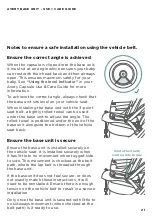
Page 21: ...towel is positioned under the end of the base unit alongside the bottom of the vehicle seat back Ensure the base unit is secure Ensure the base unit is installed securely on the vehicle seat It is installed securely when it has little to no movement when tugged side to side This movement is checked at the belt path where the lap belt is threaded through the base unit If the base unit does not feel...

Page 22: ...removed without interference Belt Buckle Length If the seat belt buckle stalk is too long to enable a secure installation it can be twisted up to three times to shorten it WARNING When installing the base unit with the vehicle belt it can only be installed using 3 point static or retractable vehicle belts WARNING If installing your base unit using the 3 point seat belt you must always stow the ISO...

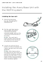
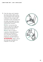
Page 23: ... in the direction of the arrow Note The small black plastic latches can be stiff but only require a tiny movement to release the connectors 3 Locate your vehicle s lower anchors in the join between the vehicle seat back and the vehicle seat base Note If the lower anchors are difficult to access insert the red ISOFIX installation guides in between the seat fabric If your lower anchors can be access...

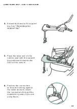
Page 24: ...tending the support leg 5 Place the base unit on the vehicle seat with the support leg positioned towards the floor of the vehicle 6 Position the connectors so they are resting against the lower anchors insert the connectors through the installation guides if you are using them ...

Page 25: ...y Pull the base unit away from the lower anchors to ensure the connection is secure Note Connecting the ISOFIX connectors with the lower anchors can require quite some pressure Note When installed correctly the small circular indicator on the side of the connector will show a green dot If not installed correctly this will show red WARNING always check the indicator matches the diagram to the right...

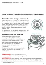
Page 26: ...e base unit has been installed securely press the support leg adjuster and extend the support leg foot to lightly touch the floor of the vehicle Important Do not over extend the support leg Ensure it does not push the base unit up off the vehicle seat There must be no gap between the base unit and the vehicle seat ...

Page 27: ...elt path and tug side to side WARNING Only install the base unit on a forward facing vehicle passenger seat WARNING An incorrectly installed child restraint can cause death or injury If you are unsure please contact Edwards Co or talk to your local child restraint technician found via the Waka Kotahi NZTA website www nzta govt nz Ensure the base unit is secure Ensure the base unit is installed sec...

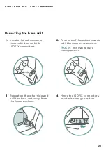
Page 28: ...n both ISOFIX connectors Removing the base unit 2 Push one of these downwards until the connector releases Note This may require some pressure 3 Repeat on the other side and pull the base unit away from the lower anchors 4 Hinge the ISOFIX connectors into their storage position ...

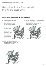
Page 29: ...nd allow it to lock securely into place Connecting the capsule to the base unit 2 Press down on all four corners of the capsule to ensure a secure connection at all connection points 3 Check the connection by attempting to lift the capsule upwards Note You will hear a distinct CLICK when the capsule connects to the base unit ...

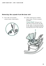
Page 30: ...e lever downwards Removing the capsule from the base unit 2 While holding the release lever down lift the capsule upwards Important Ensure the capsule is lifted high enough to be clear of the metal hooks in the base unit before pulling it away and out of the vehicle ...

Page 31: ...rness slot in the Avery Capsule s back rest Maximum Head Height The top of your baby s head must rest at least 2 5cm below the top of the Avery Capsule s shell If your child has reached any one of these limits above they have outgrown the Avery Capsule Harness Fit A secure harness reduces your child s movement in the event of a crash Ensure the Avery Capsule s harness has no slack across the hips ...

Page 32: ...y Base Unit IMPORTANT NEVER lubricate or oil any part of the Avery Base Unit NEVER use solvents harsh detergents or washing up liquids NEVER allow the Avery Base Unit to come into contact with corrosive substances such as battery acid or petroleum products Corrosion is not covered under our warranty see the Warranty in this Instruction Manual NEVER clean any part of the Avery Base Unit with abrasi...

Page 33: ...e heavy items on top of the Avery Base Unit This may distort the plastic Check regularly for wear and tear Check regularly for wear and tear on all Avery Base Unit parts Inspect your Avery Base Unit regularly Get your Avery Base Unit inspected regularly to maintain it Regular inspection ensures the locking devices are working correctly and essential components are secure Using the Avery Base Unit ...

Page 34: ...er 2021 The Avery Base Unit has a 7 year life from its date of manufacture Therefore this example has an expiry date of 15 October 2028 The Avery Base Unit must not be used if it has passed its expiry date Note The date above is an example only and does not indicate the manufacture date of the base unit purchased with this manual Clock 1 Numbered 1 30 Clock 2 Numbered 1 12 Clock 3 6 sequential num...

Page 35: ...t not following instructions transportation damage including airline or freight damage poorly maintained product dropped goods negligence second hand product modified product colour fading over inflation mould damage to handle foam in use or fabric cuts and tears Our warranty also does not cover tyre punctures or corrosion to frames or fasteners as a result of atmospheric or environmental conditio...

Page 36: ...BABY COM Come along on the journey Visit our comprehensive support centre online edwardsandcobaby zendesk com hc en us Designed with love Watch helpful instructional videos edwardsandcobaby youtube com c EdwardsCo ...

Reviews: