Contraindications
There are no absolute contraindications for using the FloTrac sensor in
patients requiring invasive pressure monitoring.
Procedure
1. Ensure that the cables are compatible with the monitors being used.
Connect the reusable cables to the monitors, and turn the monitors
on to allow the electronics to warm up.
2. Using aseptic technique, remove the sensor and kit from the sterile
packaging.
3. Add additional components as needed to complete the monitoring
system per hospital policy.
4. Ensure that all connections are secure.
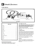
5. Connect the sensor cable with the white shield to the reusable cable
appropriate for the pressure monitor.
6. Connect the sensor cable with the green shield to the Edwards’
FloTrac connecting cable.
7. Remove all air from the heparinized IV flush solution bag per hospital
policy.
Caution:
If all air is not removed from the bag, air may be forced into
the patient’s vascular system when the solution is exhausted.
8. Close the roller clamp on the IV set and connect the IV set to the IV
flush bag. Hang the bag approximately 2 feet (60 cm) above the
patient. This height will provide approximately 45 mmHg of pressure
to prime the setup.
9. Fill the drip chamber halfway with flush solution by squeezing the
drip chamber. Open the roller clamp.
10. Flow is provided by pulling on the Snap-Tab device and discontinued
by releasing the Snap-Tab device.
11. For kits with IV sets attached, open the sensor vent port by turning
the stopcock handle. Deliver flush solution first through the sensor
and out through the vent port, then through the remaining kit by
turning the appropriate stopcocks. Remove all air bubbles.
Caution:
Significant distortion of the pressure waveform or air
emboli can result from air bubbles in the setup.
12. Replace all vented caps on sideports of the stopcocks with
nonvented caps.
13. Mount the sensor on an IV pole using the appropriate clamp and
holder. Snap sensor into place in holder.
14. Pressurize the IV flush solution bag. Flow rate will vary with pressure
across the flush device. The flow rate with the IV bag pressurized to
300 mmHg: 3 ± 1 ml/hr.
15. Connect pressure tubing to the catheter per manufacturer’s
instructions.
16. Flush system per hospital policy.
Caution:
After each fast-flush operation, observe the drip chamber to
verify that the continuous flush rate is as desired (see
Complications
).
Zeroing and Calibration
1. Adjust the level of the sensor vent port (the fluid-air interface) to
correspond to the chamber where pressure is being measured. For
example, in cardiac monitoring, zero at level of the right atrium. This
is at the phlebostatic axis, determined by the intersection of the
midaxillary line and the fourth intercostal space.
2. Remove the non-vented cap and open the vent port to the atmosphere.
3. Adjust the pressure monitor to read zero mmHg.
4. Check pressure monitor calibration using procedure recommended
by the monitor manufacturer.
5. Close the vent port to the atmosphere and replace the nonvented cap.
6. System is ready to begin monitoring pressure.
Testing Dynamic Response
The assembly may be tested for dynamic response by observing the
pressure waveform on an oscilloscope or monitor. Bedside
determination of the dynamic response of the catheter, monitor, kit, and
sensor system is done after the system is flushed, attached to the
patient, zeroed, and calibrated. A square-wave test may be performed
by pulling the Snap-Tab device and releasing quickly.
Note:
Poor dynamic response can be caused by air bubbles, clotting,
excessive lengths of tubing, excessively compliant pressure tubing,
small bore tubing, loose connections, or leaks.
Routine Maintenance
Follow hospital policies and procedures for frequency of zeroing the
sensor and pressure monitor and for replacing and maintaining pressure
monitoring lines. The FloTrac sensor is precalibrated and has a
negligible drift with time (see
Specifications
).
1. Adjust zero pressure reference each time level of the patient is
changed.
Caution:
When rechecking zero or verifying accuracy, ensure that
the non-vented cap is removed before opening the sensor vent port
to the atmosphere.
2. Periodically check fluid path for air bubbles. Ensure that connecting
lines and stopcocks remain tightly fitted.
3. Periodically observe the drip chamber to verify that the continuous
flush rate is as desired.
4. The Centers for Disease Control recommends replacing disposable
or reusable transducers at 96-hour intervals. Replace other
components of the system, including the tubing, continuous-flush
device, and flush solution, at the time the sensor is replaced.
Warnings
•
Do not use the flush device during intracranial pressure
monitoring.
•
High pressures, which may be generated by an infusion pump
at certain flow rates, may override the flush device restriction,
resulting in fast flushing at the rate set by the pump.
2


