
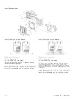

Figure 1: Mounting diagram
Figure 2: Typical one-circuit wiring diagram
Figure 3: Typical two-circuit wiring diagram
Polarity is shown in the active state.
(1) From voltage source.
(2) To next device or end of line resistor.
The strobe must be connected to signal circuits having a constant
(non-coded) voltage output. The horn must be connected to a
continuous voltage when it is set to sound a temporal tone; it may be
connected to either a pulsed or continuous voltage when set to sound
a steady tone.
Caution:
Electrical supervision requires wire run to be broken at each
terminal. Do not loop signaling circuit field wires around terminals.
Polarity is shown in the active state.
(1) From voltage source.
(2) To next device or end of line resistor.
The horn and strobe must be connected to a signal circuit having a
constant (non-coded) voltage output.
Caution:
Electrical supervision requires wire run to be broken at each
terminal. Do not loop signaling circuit field wires around terminals.
2 / 3
P/N 3100285 • REV 2.0 • ISS 22JUL11


