background image

P/N 3101204 • REV 03 • REB 28JAN13 


3 / 6 

LED specifications 


Voltage 

24 VDC 

Standby current 

4 mA 

Active LED current 

One LED expander 
Two LED expanders 

 
48 mA 
96 mA 

Operating environment 
Temperature 
Humidity 

 
32 to 120°F (0 to 49°C) 
0 to 93% RH, noncondensing at 90°F 
(32°C) 

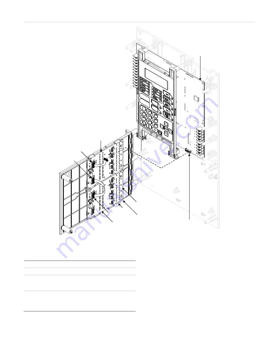
Figure 3: LED display expander installation 

J6

J2

J1

J1

Clip

LED

PCB

Top LED 
display
expander
assembly

Bottom LED
display
expander
assembly

Alignment
pin

Main circuit
board


Summary of Contents for D16L-Fa

Page 1: ...e zone LEDs LED expander 1 LED expander 2 LED installation 1 Power down the panel and disconnect the batteries 2 Remove the screws securing the right and left side LED display expander assemblies and then remove each expander assembly as shown in Figure 2 3 Remove the blank overlay from the front of the LED display expander and then install the new annunciator overlay in its place as shown in Figu...

Page 2: ... P N 3101204 REV 03 REB 28JAN13 Figure 2 LED display expander assembly installation 6 plastite screw Bottom LED display expander assembly Top LED display expander assembly Blank overlay Annunciator overlay ...

Page 3: ...ED expander Two LED expanders 48 mA 96 mA Operating environment Temperature Humidity 32 to 120 F 0 to 49 C 0 to 93 RH noncondensing at 90 F 32 C Figure 3 LED display expander installation J6 J2 J1 J1 Clip LED PCB Top LED display expander assembly Bottom LED display expander assembly Alignment pin Main circuit board ...

Page 4: ...e l extenseur d affichage DEL puis enlevez chaque montage comme indiqué la Figure 2 3 Enlevez le couvercle vide à l avant de l extenseur d affichage DEL puis installez le nouvel indicateur à sa place comme indiqué la Figure 2 4 Placez la carte de circuits imprimés du DEL sur le montage de l extenseur avec les trous de la carte alignés avec les broches du montage comme indiqué la Figure 3 5 Fixez l...

Page 5: ...8 mA 96 mA Cadre opérationnel Température Humidité 0 à 49 C 32 à 120 F 0 à 93 RH non condensation à 32 C 90 F Figure 3 Installation de l extenseur d affichage DEL Montage de l extenseur du voyant DEL supérieur Montage de l extenseur du voyant DEL inférieur Voyant DEL de la cart de circuits imprimés Carte de circuits imprimés J1 J2 J1 Broche Axe d alignement J6 ...

Page 6: ...6 6 P N 3101204 REV 03 REB 28JAN13 ...

Reviews: