D397-21-880 Issue G
Page 30
© Edwards Limited 2009. All rights reserved.
Edwards and the Edwards logo are trademarks of Edwards Limited.
Operation
4.9
Alarms
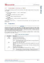
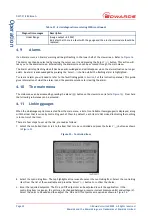
If an Alarm occurs, an 'Alarms' warning will begin flashing in the lower half of the view screen. Refer to
The Alarm can then be selected by moving the cursor over it and pressing the 'Select' ( ) button. This action will
take you to the Alarms screen. Alternatively the Alarms screen can be accessed through the main menu.
The Alarm will stop flashing when it has been acknowledged and will disappear when the alarm situation no longer
exists. An alarm is acknowledged by pressing the 'Select' () button whilst the flashing alarm is highlighted.
To clear an alarm you will need to refer to the fault finding guide in
of this instruction manual. This guide
gives information of what the alarm is and the possible solutions for clearing the alarm.
4.10
The main menu
The main menu can be accessed by pressing the 'Menu' ( ) button on the view screen (refer to
). From here
the following sub-menus can be accessed.
4.11
Linking gauges
When the Link Gauges option is selected from the main menu, a list of controllable items (gauges) is displayed, along
with the item that is currently controlling each of them. By default, each item is 'Not Linked' indicating that nothing
is in control of the item.
There are four steps to set up the link, proceed as follows:
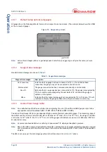
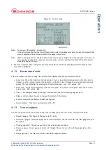
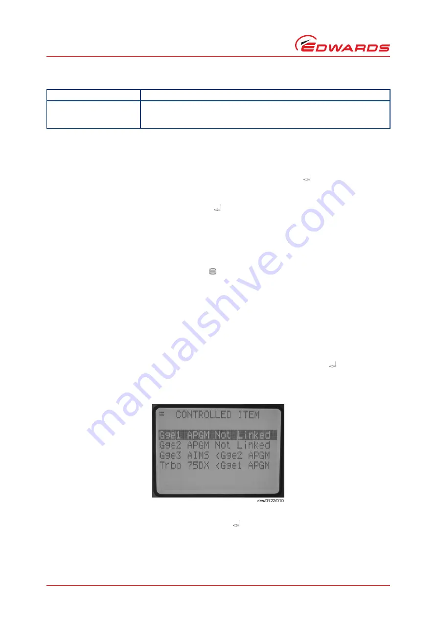
1. Select the controlled item. Scroll to the item that is to be controlled and press the 'Select' ( ) button as shown
Figure 23 - Controlled item
2. Select the controlling item. The top highlighted line is used to select the controlling item. Select the controlling
item from the list of those available and press the 'Select' ( ) button to confirm the choice.
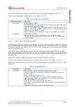
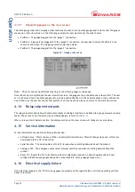
3. Enter the required setpoints. The 'On' and 'Off' setpoints can be adjusted to suit the application. If the
controlling item is a gauge, the units can be changed between pressure (current pressure units) and voltage (V).
Select the units to be used and then adjust the 'On' and 'Off' setpoints as required as shown in
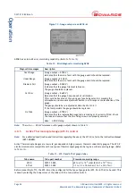
Under Range
(Gauge output
<
0.950V)
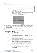
Indicates that there is a fault with the gauge and the electronics module should be
replaced.
Table 21 - Error/diagnostic monitoring WRG (continued)
Diagnostic messages
Description


