background image

© Edwards Limited 2009. All rights reserved. 

Page 35

Edwards and the Edwards logo are trademarks of Edwards Limited.

Storage and disposal

D397-21-880 Issue G

6

Storage and disposal

6.1

Storage

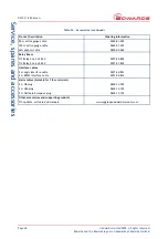
Store the Controller in clean dry conditions in accordance with the technical specifications. Refer to 

Section 2

 of the 

main manual on the CD.

6.2

Disposal

Dispose of the Controller and any components safely in accordance with all-local and national safety and 
environmental requirements.

Alternatively, you may be able to recycle the Controller and/or cables; contact Edwards or your supplier for advice 
(also see below).

The Controller and associated cables are within the scope of the European Directive on Waste Electrical and 
Electronic Equipment, 2002/96/EC. Edwards offer European customers a recycling service for the Controller/cables 
at the end of the product’s life. Contact Edwards for advice on how to return the Controller/cables for recycling.

WARNING

Do not incinerate the Controller. If the Controller is heated to very high temperatures, dangerous 
gases may be emitted and internal components may explode.

Summary of Contents for D397-00-000

Page 1: ...D397 21 880 Issue G Instruction Manual Instrument Controller Description Item Number TIC Instrument Controller D397 00 000 ...

Page 2: ...declaration relates is in conformity with the following standard s or other normative document s EN61010 1 2001 Safety Requirements for Electrical Equipment for Measurement Control and Laboratory Use Part 1 General Requirements EN61326 1 2006 Electrical Equipment for Measurement Control and Laboratory Industrial location Use EMC Requirements Class B Emissions and fulfils all the relevant provision...

Page 3: ...ing the serial interface 14 4 Operation 17 4 1 Front panel description 17 4 2 Menu structure 18 4 3 Navigating the menu 19 4 4 The view screen 19 4 5 Turning gauges and relays on off 19 4 6 Changing list items 20 4 7 Changing numerical values 20 4 7 1 Entering negative components e g 5 00E 03 21 4 8 Gauge setup 21 4 8 1 Default setup options all gauges 22 4 8 2 Gauge status messages 22 4 8 3 Activ...

Page 4: ... 4 2 Pin connection for a 15 way sub minature D type socket 4 3 Pin connections for a 9 way sub miniature D type socket 6 4 Pin connection for 4 way analogue output connector 6 5 Bench mounted TIC dimensions mm 10 6 Front panel removal 10 7 Rack mounting of a TIC 11 8 Panel cut out drawing 11 9 Rear panel connections 12 10 IBM PC RS232 interface 9 way 14 11 IBM PC RS232 interface 25 way 14 12 RS48...

Page 5: ...ist 9 7 Front panel symbols and their functions 17 8 Default setup options all gauges 21 9 Gauge status messages 22 10 Error diagnostic monitoring APG 23 11 Setup options APGX 23 12 Error diagnostic monitoring APGX 24 13 ATC D and ATC M gauge tubes 24 14 Error diagnostic monitoring ATC E 25 15 Setup options ASG 25 16 Error diagnostic monitoring ASG 26 17 Error diagnostic monitoring AIM 27 18 Setup...

Page 6: ...This page has been intentionally left blank D397 21 880 Issue G Page iv Edwards Limited 2009 All rights reserved Edwards and the Edwards logo are trademarks of Edwards Limited ...

Page 7: ...rs on the controller 1 2 Product description The Instrument Controller is provided with a large clear graphics display easy to use control interface via a touch sensitive keypad an RS232 485 interface for control and data monitoring on a remote PC and a logic interface for interface with associated system hardware The compatible instruments that can be used with the Instrument Controller are liste...

Page 8: ...D397 21 880 Issue G Page 2 Edwards Limited 2009 All rights reserved Edwards and the Edwards logo are trademarks of Edwards Limited This page has been intentionally left blank ...

Page 9: ...elf protecting and has no user replaceable fuse The unit will recover once any overload is removed Earth Stud M4 Ambient operating temperature range 0 C to 40 C Ambient storage temperature range 30 C to 70 C Maximum ambient operating humidity Max 90 RH non condensing at 40 C Maximum operating altitude 3000 m max IP rating 20 Weight TIC Instrument Controller 1 3 kg Connector type FCC RJ45 8 way ref...

Page 10: ...out Pin Allocation 1 Power supply positive 2 Power supply common 3 Signal input 4 Identification 5 Signal common 6 Control line 1 7 Control line 2 8 N C Connector type 25 way sub miniature D type socket refer to Figure 2 Power supply 24 V d c Maximum output power 5 W Control output active 1 1 V d c Iout 20 mA 0 8 V d c Iout 2 mA inactive open internal pull up to 24 V Control input low 2 0 V d c Io...

Page 11: ...Analogue output common 15 Setpoint 2 output 16 Setpoint 3 output 17 Do not connect 18 Alarm output 19 Setpoint 6 output 20 Gauge 2 enable input 21 Gauge 3 enable input 22 Do not connect 23 Do not connect 24 Do not connect 25 System interlock input SYSI Connector type 9 way sub miniature D type socket refer to Figure 3 RS232 transmit mark 8 V Iout max 8 mA space 8 V Iout max 8 mA RS232 receive mark...

Page 12: ...tor Table 4 Serial communications connector pin out Pin Allocation 1 N C 2 RS232 transmit 3 RS232 receive 4 N C 5 RS232 common 6 N C 7 N C 8 RS485 data A 9 RS485 data B Connector type Phoenix 2 5 mm 4 way mating half Phoenix FK MC 0 5 4 ST 2 5 available from Edwards as 5000 17005 Short circuit protection All signals Max load Gauge signals 1 mA Common 3 mA Output voltages Gauge connected Gauge sign...

Page 13: ...ge 7 Edwards and the Edwards logo are trademarks of Edwards Limited Technical data D397 21 880 Issue G Table 5 Pin allocation for analogue outputs Pin Allocation Gauges 1 3 Top Ports 1 Gauge 1 signal 2 Gauge 2 signal 3 Gauge 3 signal 4 Common 0 V ...

Page 14: ...D397 21 880 Issue G Page 8 Edwards Limited 2009 All rights reserved Edwards and the Edwards logo are trademarks of Edwards Limited This page has been intentionally left blank ...

Page 15: ...ed in Section 6 1 3 2 Fitting the controller CAUTION Rubber feet must be fitted Figure 5 item 1 so that there are correct clearances for air circulation If you do not the performance of the Controller may be affected at high operating temperatures The Controller can be used on a bench top or can be fitted in a rack or cabinet Figure 5 shows the dimensions of the TIC that are required for bench top...

Page 16: ...150 mm at the rear for cables Allow 50 mm top and bottom and 15 mm to the sides for sufficient air circulation Do not cover any of the ventilation holes CAUTION This unit is IP20 rated Please ensure that the unit is not installed where fluids can enter into the controller CAUTION The unit must be supported at the rear Figure 6 Front panel removal WARNING Ensure that all electrical wiring is safely...

Page 17: ... 2 z Slide the Controller into the 19 rack or panel cut out The use of 19 rack guide rails Figure 7 item 2 and support at the rear of the Controller is recommended as shown in Figure 7 The panel cut out information is defined in Figure 8 z Fix the Controller in place using the four screws removed previously Figure 7 item 1 Figure 7 Rack mounting of a TIC Figure 8 Panel cut out drawing 1 Fixing scr...

Page 18: ... provides protective earthing for electrical safety If this is not the case or if additional earth bonding is required then the earth stud on the rear of the Controller Figure 9 item 4 should be connected to your vacuum system earth Connect a suitably earthed cable between the two nuts fitted to the earth stud on the rear of the TIC Note Do not remove the bottom nut from the earth stud WARNING Hig...

Page 19: ...ng the operation of the TIC and the associated vacuum system from external sources Gauge 1 2 3 Enable Pins 9 20 21 The gauge enable inputs can be used to control the operation of the gauges If gauge enable is open the associated gauge cannot be turned on and will turn off if it is operating To enable the gauges connect the required gauge enable line to 0 V Note Only gauges that can be turned on an...

Page 20: ...t drawn from 24 V pin on logic connector should be 208 mA maximum 3 3 5 Connecting the serial interface The TIC has two serial communications protocols built in RS232 and RS485 RS232 is the simplest interface and can be used to allow a host PC to control the TIC RS485 allows a host PC to control a small network of TICs 3 3 5 1 Connecting RS232 The TIC is fitted with a 9 way D type socket on the re...

Page 21: ...ns are tied together If differences exist in the local ground voltage damage could occur If the TICs being networked are liable to experience different ground potentials a suitable RS485 isolator should be connected between them Use shielded cable for the interface to reduce interference problems and limit the length of the RS485 link to less than 1000 metres Long links may require the addition of...

Page 22: ...D397 21 880 Issue G Page 16 Edwards Limited 2009 All rights reserved Edwards and the Edwards logo are trademarks of Edwards Limited This page has been intentionally left blank ...

Page 23: ... Cycle a selected list item upwards DOWN Move down through a menu Cycle selected numerical values down Cycle a selected list item downwards SELECT Enter the highlighted sub menu Edit the highlighted list or numerical item Move to the next digit of a numerical value Jump to the setup screen for the highlighted gauge MENU Switch between the default view screen and the main menu Exit the current sub ...

Page 24: ...logo are trademarks of Edwards Limited Operation 4 2 Menu structure Figure 14 and 15 show the view screen shortcuts and menu structure for the TIC They also give an indication as to what buttons will take you where within the menu layout Figure 14 View screen shortcuts Figure 15 Menu structure ...

Page 25: ...ected TIC automatically identifies the gauge and indicates that a new gauge has been detected as shown in Figure 16 Figure 16 New gauge connected In this example new gauges have been plugged into channels 1 and 2 Scroll up down to the selected gauge channel and press the Select button The display will identify the gauge type and display either an output or message Gauges which measure up to atmosp...

Page 26: ...m allowing another item to be selected for adjustment Pressing the Menu button will cancel the adjustment and return the highlight to the row item allowing another item to be selected for adjustment 4 7 Changing numerical values To change a numerical item scroll to the required line and press the Select button The first number will then be highlighted and can be changed using the up and down arrow...

Page 27: ...t button accesses the Gauge Setup screen Refer to Table 8 First enter the number using the and buttons as above 5 00E 0 Then use the menu button to move to the character 5 00E 03 Use the buttons to change the character to 5 00E 03 Finally press the select button three times to complete the entry Table 8 Default setup options all gauges Menu option Description Gauge Indicates type of gauge connecte...

Page 28: ... 10 mbar to 10 4 mbar 7 5 to 7 5 x 10 5 Torr All of the gauges will indicate pressure up to 1000 mbar 750 Torr at reduced accuracy Note At pressures above 600 mbar sensitivity is reduced and TIC displays atmospheric pressure Note Before the APG is used and periodically thereafter atmosphere and vacuum calibration should be carried out in accordance with the directions shown in the Instruction Manu...

Page 29: ... has menu options in addition to those shown Refer to Default setup options all gauges Section 4 8 1 Refer to Table 11 Table 10 Error diagnostic monitoring APG Diagnostic messages Description Over Range Gauge output 11 000 V Indicates that either the measured gas pressure is outside the range of the gauge or that there is a fault with the gauge Clear the error message reduce the process pressure t...

Page 30: ...agnostic monitoring APGX Diagnostic messages Description Over Range Gauge output 9 750 V Indicates that there is a fault with the gauge and it should be replaced Under Range Gauge output 0 300 V Indicates that there is a fault with the gauge and it should be replaced Filament Fail Gauge output 9 500 V Indicates that the gauge filament is broken The gauge should be replaced Cal Error Gauge output 9...

Page 31: ...SG has menu options in addition to those shown Refer to Default setup options all gauges Section 4 8 1 Refer to Table 15 and Figure 20 Table 14 Error diagnostic monitoring ATC E Diagnostic messages Description Over Range Gauge output 11 000V Indicates that either the measured gas pressure is outside the range of the gauge or that there is a fault with the gauge Clear the error message reduce the p...

Page 32: ...M X outputs low external magnetic field AIM SL and AIM XL variants for use on sensitive scientific instruments and special bakeable tubes for use in UHV applications There are no additional setup options for AIM Refer to Default setup options all gauges Section 4 8 1 Please refer to Table 17 for the error and diagnostic information for the AIM gauge Table 16 Error diagnostic monitoring ASG Diagnos...

Page 33: ...he range of the gauge and press Cycle If the error persists there is a fault with the gauge and the electronics module should be replaced Under Range Gauge output 0 025 V Indicates that there is a fault with the gauge or cable Replace the cable and if the fault persists the electronics module should be replaced Striking Indicates that the gauge is attempting to strike TIC will continue in this mod...

Page 34: ...10 4 Torr WRG has menu options in addition to those shown Refer to Default setup options all gauges Section 4 8 1 Refer to Table 20 and Figure 22 Table 19 Error diagnostic monitoring AIM Diagnostic messages Description Over Range Gauge output 9 800 V Indicates that there is a fault with the gauge and the electronics module should be replaced Over Pressure Gauge output 9 700 V Indicates that the ga...

Page 35: ...x 10 4 mbar 7 5 x 10 5 Torr Table 21 Error diagnostic monitoring WRG Diagnostic messages Description Over Range Gauge output 10 600 V Indicates that there is a fault with the gauge and it should be replaced Not Struck Gauge output 1 300 V Indicates that the magnetron part of the gauge has not struck The gauge tube should be inspected for signs of contamination or debris If the anode and cathode ar...

Page 36: ...g sub menus can be accessed 4 11 Linking gauges When the Link Gauges option is selected from the main menu a list of controllable items gauges is displayed along with the item that is currently controlling each of them By default each item is Not Linked indicating that nothing is in control of the item There are four steps to set up the link proceed as follows 1 Select the controlled item Scroll t...

Page 37: ...e able to change any of the setups however the operator is still able to scroll through the menus and start and stop pumps The lock is disabled by entering the 3 digit unlock code Lock 501 unlock 147 z Panel Lock This function completely locks the front panel An operator will only be able to see the view screen Lock 509 unlock 824 z The 0 10 V analogue output on the logic interface can be set to f...

Page 38: ...olled to as the user has chosen that position 2 will not be shown when you return to the main view screen 4 14 Relay setpoint outputs The relay setpoints option allows the setpoint outputs on the logic interface to be linked to a gauge pressure or pump speed They are set up in the same way as Linking Gauges refer to Section 4 11 When a relay setpoint becomes active the display section on the view ...

Page 39: ...manual Filament Fail Refer to appropriate Section in manual Mag Fail Refer to Table 21 Striker Fail Refer to Table 21 Cal Error Refer to Table 12 Initialising Refer to Table 19 Emission Error Refer to Table 19 Over Pressure Refer to Table 19 ASG Cant Zero Refer to Table 16 General SYSI Inhibit The system interlock has been disconnected Please check that the logic interface plug is connected correc...

Page 40: ...e Controller and the TIC PC monitor program will be updated as part of Edwards ongoing development program The updates and associated instruction manual can be found by visiting www upgrades edwardsvacuum com 5 5 Factory defaults The following is a list of factory default settings for the TIC Table 23 Factory default settings Menu option Default Gauge and relay slaving not slaved Gas type Nitrogen...

Page 41: ...environmental requirements Alternatively you may be able to recycle the Controller and or cables contact Edwards or your supplier for advice also see below The Controller and associated cables are within the scope of the European Directive on Waste Electrical and Electronic Equipment 2002 96 EC Edwards offer European customers a recycling service for the Controller cables at the end of the product...

Page 42: ...D397 21 880 Issue G Page 36 Edwards Limited 2009 All rights reserved Edwards and the Edwards logo are trademarks of Edwards Limited This page has been intentionally left blank ...

Page 43: ...e tester If the customer is unable to carry out this repair the Controller should be returned to Edwards for a full repair and safety re test 7 3 Accessories Table 24 shows the range of accessories that can be purchased Spare Item Number TIC Front Bezel Kit D397 00 803 TIC Logic Interface D397 00 850 Front Panel Assembly D397 00 822 Table 24 Accessories Product Description Ordering Information TIC...

Page 44: ...xes TIC Relay box 3 x 240 V D397 00 804 TIC Relay box 6 x 240 V D397 01 804 Interface cables 2 m Logic interface cable D397 00 833 2 m RS232 interface cable D397 00 834 Mains cables Suitable for TIC controllers 2 m UK plug D400 13 025 2 m USA plug D400 13 120 2 m Northern European plug D400 13 120 Other accessories and supporting products TIC updates software and manuals www upgrades edwardsvacuum...

Page 45: ...ure 32 Entering negative components 21 F Factory defaults 34 Fault finding 33 Fitting the controller 9 Front panel display 17 Fuse 3 G Gauge order set up 32 Gauge setup 21 I Installation 9 L Linking gauges 30 Logic interface 4 M Maintenance 33 Mechanical data 3 Menu structure 18 O Operating and storage data 3 Operation 17 Organising gauges on the view screen 32 P Pin allocation for analogue output...

Page 46: ...D397 21 880 Issue G Page 40 Edwards Limited 2009 All rights reserved Edwards and the Edwards logo are trademarks of Edwards Limited This page has been intentionally left blank ...

Reviews: