A541-11-880 Issue A
Page 22
© Edwards Limited 2010. All rights reserved.
Edwards and the Edwards logo are trademarks of Edwards Limited.
Installation
The pumping system has an electrical connector locking mechanism
, which requires the use of a suitable
screwdriver to release. The pumping system is supplied with a protective cover fitted and the locking mechanism
may be applied. Use the following procedure to fit your electrical supply cable:
1. Refer to
. Slacken off the locking screw (item 2) by a few turns to loosen the locking mechanism, if
necessary.
2. Move the locking mechanism (item 1) to the right as far as possible so that it clears the lever (item 3).
3. Push the lever (item 3) to release the protective cover.
4. Remove the protective cover and fit your electrical supply cable.
5. Pull the lever forwards to secure your electrical supply cable connector in place.
6. Move the locking mechanism to the left as far as possible so that it prevents the lever from actuating.
7. Tighten the locking screw (item 2) to firmly hold the locking mechanism in place.
8. Connect the other end of your electrical supply cable to your electrical supply through a suitable isolator.
3.9
Connect to your emergency stop circuit
CAUTION
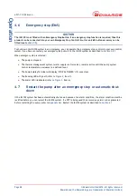
The iXL120 is supplied with an emergency stop circuit. If an emergency stop function is required, then this
product can be connected into your own Emergency Stop Control Circuit or the emergency stop button accessory
can be used (see
).
Note:
If you do not connect to your own control equipment, you must fit the external EMS plug, supplied, to the
EMS connector (
, item 15) on the rear of the iXL120 system. If you do not, you will not be able to
operate the iXL120 system.
If required, you can connect your own control equipment to the iXL120 system to shut it down in an emergency
using the EMS connection (
, item
15
). The emergency stop control must be compliant with
IEC 60947-5-1 (This should be a red self latching mushroom push button on a yellow background). An EMS button
accessory is available, refer to
3.10
Connect to your control equipment
CAUTION
Do not connect voltages greater than 30 V to the Tool interface control. If you do, the interface control will not
comply with the low voltage safety directive and the equipment may be damaged.
The pump may be connected to your control equipment through the MicroTIM (if fitted). The MicroTIM is supplied
with a protective plastic cap fitted. Remove this before connecting the mating connector. Several different tool
interfaces are available. The label next to the tool connector identifies which type of MicroTIM is fitted, refer to
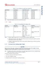
to identify the connectors types and mating tool connector kits available (not supplied with the pump).
for a definition of the input signals to the pump system.
WARNING
Tool interface control signals are for control purposes only and should not be relied upon for safety
critical functions.


