background image

o

If multiple miniature circuit breakers supply dangerous voltages to the device or load,
couple the miniature circuit breakers or label them with a warning, to ensure disconnection
is guaranteed.

o

Connect bus line with connecting terminal.

i

DALI devices can be connected to various phase conductors.

Operation in emergency lighting systems

The device can be used in decentrally-powered or in centrally-powered emergency lighting
systems.
In decentrally-powered emergency light systems, emergency luminaires with individual batteries
and special DALI devices are used. 

i

Observe the number of DALI devices in the emergency luminaires used.

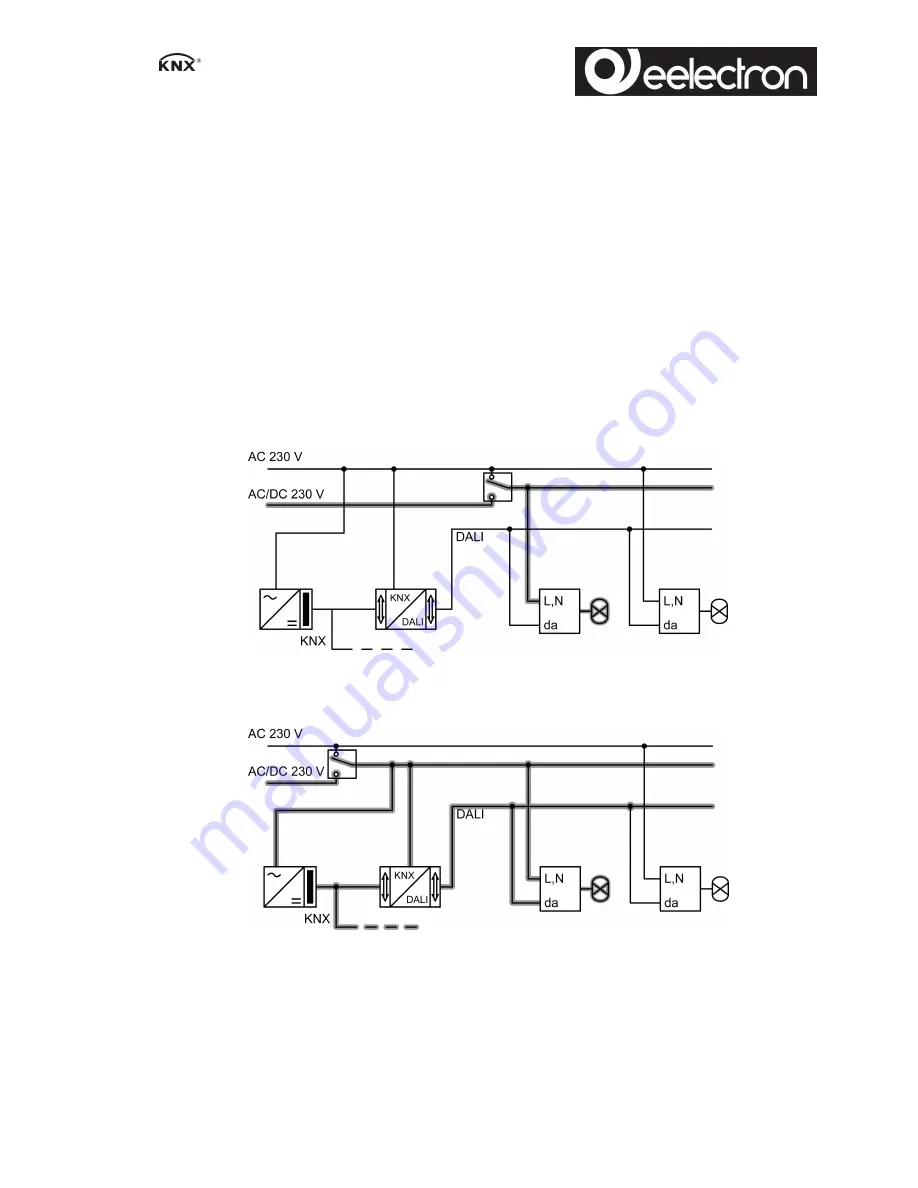
Emergency lighting systems with a central safety supply are required in buildings larger than
2000 m². Depending on the scope of functions of the system, only the emergency luminaires
are supplied by the central safety supply (Figure 4), or the KNX system and DALI gateway are
also supplied (Figure 5). In the latter case, in emergency operation, the DALI gateway can
transmit the appropriate fault messages to a central system and other DALI gateways in the
system.

Figure 4: Emergency luminaires supplied through a central safety supply

Figure 5: Emergency luminaires, KNX system and DALI gateway supplied through a central

safety supply

Installing the cover

It is necessary to install a cover to protect the bus connection against hazardous voltages in the
connection area.

6/9

IC00P01DAL - 

DALI gateway

Summary of Contents for IC00P01DAL

Page 1: ...ing ensure safe isolation between KNX and DALI These instructions are an integral part of the product and must remain with the end customer 2 Device components Figure 1 1 Button field for manual operation 2 Programming button and LEDs 3 KNX connection 4 Display of DALI devices or DALI group 5 Connection for mains supply 6 DALI output 3 Function System information This device is a product of the KN...

Page 2: ...ames Read out DALI device state via KNX e g brightness or luminaire error Manual operation of the DALI groups Restraint Feedback of switching state and brightness value in bus and manual mode Collective feedback Central switching function Disabling function for each DALI group Separate ON and OFF delay Staircase lighting timer with run on time Corridor function when combined with motion detectors ...

Page 3: ...s Bus operation Operation via push button sensors or other bus devices Short term manual operation Manual operation locally with button field automatic return to bus operation Continuous manual mode Exclusively manual operation on the device i No bus operation is possible in manual mode i No manual mode is possible in case of bus failure i After a bus failure and restoration the device switches to...

Page 4: ...he desired DALI number The LEDs ON n and OFF o indicate the status o Operate output with ON n or OFF o button Short switch on off Long dim brighter darker Release Stop dimming The LEDs ON n and OFF o indicate the status i Short term manual operation after running through all of the available DALI numbers the device exits manual mode after another brief press i The display 4 firstly shows the numbe...

Page 5: ...tting the device Observe the temperature range Ensure adequate cooling o Mount device on DIN rail Output terminals must be at the top Connecting the device Figure 3 Control cable appropriate type cross section and routing for the specifications for 250 V cables DALI and mains voltage wires can be run together in a cable e g NYM 5x1 5 mm i DALI participants from some manufacturers have expanded fun...

Page 6: ...rgency luminaires used Emergency lighting systems with a central safety supply are required in buildings larger than 2000 m Depending on the scope of functions of the system only the emergency luminaires are supplied by the central safety supply Figure 4 or the KNX system and DALI gateway are also supplied Figure 5 In the latter case in emergency operation the DALI gateway can transmit the appropr...

Page 7: ... Load the address and the application software o Switch on mains voltage o Switch on the bus voltage o Assign physical address and note on the device label o Commission DALI system using commissioning software i For more detailed information on commissioning of the DALI system see the technical product information for this device o Load the application software into the device i No programming is ...

Page 8: ...ode Rated voltage KNX DC 21 32 V SELV Power consumption KNX typical 150 mW Connection type for bus Connection terminal 6 2 Troubleshooting Display shows Er connected DALI devices have no function no operation possible Cause Mains voltage on DALI cable Installation error Disconnect device and connected DALI devices from mains voltage and disconnect bus voltage Correct installation Display shows bc ...

Page 9: ...eset Disconnect device from bus switch on again after approx 5 seconds Cause 4 Application software missing or faulty Check programming and correct 6 3 Warranty We reserve the right to make technical and formal changes to the product in the interest of technical progress We provide a warranty as provided for by law Please send the unit postage free with a description of the defect to our central c...

Reviews: