background image


Pagina 1 di 24


Transponder Reader 

TR22A01KNX 
TR22A11KNX 


Product Handbook 


Product: 

Transponder Reader


Order Code:

 TR22A01KNX - TR22A11KNX 

Application Program ETS: 

EEL_RDT1_10 Transponder Card Reader 


Summary of Contents for TR22A01KNX

Page 1: ...Pagina 1 di 24 Transponder Reader TR22A01KNX TR22A11KNX Product Handbook Product Transponder Reader Order Code TR22A01KNX TR22A11KNX Application Program ETS EEL_RDT1_10 Transponder Card Reader ...

Page 2: ...mension drawing 5 2 4 Mounting and wiring hints 6 3 Product and functional overview 7 4 Parameters 9 4 1 Parameter window General Configurations 9 4 2 Parameter Window Relay 1 Configuration 11 4 3 Parameter Window Relay 2 Configuration 14 4 4 Parameter Window Input 1 Configuration 15 5 Communication Objects 18 6 Application Notes 22 ...

Page 3: ...ly open Standard for home and building automation Eelectron philosophy of comprehensive aesthetic design and engagement in developing highly innovative devices matched with KNX Interoperability and compliance with international requirements has engendered Eelectron s distinct reputation Eelectron experience is devoted to end users with a constant training activity assistance on products and a cont...

Page 4: ...ccording to EN 60529 III according to EN 61140 III according to EN 60664 1 CE Mark and Certifications CE EIB KNX In accodance with EMC and Low Voltage guidelines According to EN 50090 1 2 Transponder Reader The Transponder Reader TR22A01KNX is an EIB KNX wall mounting device suitable to access control application This device can be used in any kind of building Hotel Hospital Offices Parking etc wh...

Page 5: ...lay2 NO 5 COM Outputs 6 IN 1 potential free 7 IN 2 potential free 8 COM Inputs 11 Bus Connection Terminal Black bus polarity Red bus polarity Operating Elements 9 Programming LED 10 Programming push button 12 Led 4 13 Led 3 14 Led 2 15 Led 1 1 2 3 4 5 6 7 8 KNX 9 10 11 Input 2 Out 2 Input 1 Interfaccia BUS KNX EIB Com 5 6 7 8 Com Bassa tensione max 60 V ac dc 2A Alimentazione 12 24 V ac dc Out 1 1...

Page 6: ...the bus connection block into the guide slot placed on the front side of this device and press the block down to the stop In order to commission the device a PC with ETS2 version V1 3 or higher is required as well as an interface to the bus e g via an RS232 interface or via a USB interface The device configuration KNX physical address assignment is done by pressing the programming push button loca...

Page 7: ...uence where the Build Number has been checked at first then the expiration data next the password ID for client guest service identification then the enabled days of week and hours range In case card reading pass all checks the door is opened the courtesy light inside is switched on and a specific 1 bit object associated to the identified class of user is sent At the same time the Transponder Read...

Page 8: ... alarm enable Input 1 and 2 Configuration Switching states ON or OFF can be set depending on input pulse adge evalutation rising or falling edge Cyclical sending option at adjustable intervals Relay 1 Configuration General Purpose or Door Open function selection Normally open or closed contact setting Time switching e g Door lock timing release Relay 2 Configuration General Purpose or Courtesy Lig...

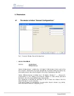
Page 9: ...his option only one single group of users are managed in the range of passwords admitted Option Different Access enables four 1 bit objects Access 1 Access 4 corresponding to the reading and entrance allowed of users whose password belongs to one of four pre defined range of passwords As a password is identified as belonging to one of these four classes than the object Access X is sent to the bus ...

Page 10: ...l Note in both cases the transponder reader always reads and checks the timing hour valid range associated to the card Send Alarm Options OFF ON Option OFF the device does not send the object Alarm Option ON the device sends the object Alarm in case of power failure after the power supply has been recovered Note this feature is useful to visualization software in order to re send data to the reade...

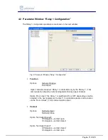
Page 11: ...Relay 1 1 bit communication object as normal independent binary output channel Option Door Open the Relay 1 is switched ON or OFF depending on option selected in the next parameter Contact if a valid transponder card is read or via the Door Unlock 1 bit communication object Contact Options Normally Open Normally Close Option Normally Opened Off telegram contact open On telegram contact closed Opti...

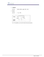
Page 12: ... object it is routed directly to the relay The Off delay that has been assigned starts at the same time Every further 1 ON that is received before the timer has elapsed resets the delay and restarts it Once the period has elapsed a 0 is passed to the output An Off telegram deletes the Off delay and is immediately routed to the output The time for the Off delay is set here This is calculated from t...

Page 13: ...Pagina 13 di 24 TimeBase Options 250ms 500ms 1Sec 1Min 1Hour Factor Options 0 10 255 Fig 4 Timing Mode e g for electrical lock pulse operating control ...

Page 14: ...pose Relay 2 is controlled only by the Relay 2 1 bit communication object as normal independent binary output channel Option Courtesy Light the Relay 2 is switched ON or OFF depending on option selected in the next parameter Contact if a valid transponder card is read or via the Courtesy Light 1 bit communication object All the other parameters are completely similar to Relay 1 Configuration setti...

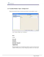
Page 15: ...o Input 2 Fig 6 Parameter Window Input 1 Configuration Mode Options Rising ON Rising OFF Falling ON Falling OFF Rising ON Falling OFF Rising OFF Falling ON Toggle ON OFF Toggle OFF ON With this parameter we can program which status we need to send to the bus ON OFF TOGGLE when a rising or falling edge is detected in the input signal ...

Page 16: ...he communication object A falling edge causes a logic 0 to be sent Rising Off Falling On A rising edge causes a logic 0 to be transferred to the communication object A falling edge causes a logic 1 to be sent Toggle ON OFF Each rising edge causes the object value to be inverted This means that a logic 1 is sent to the communication object after the first rising edge The next one sends a logic 0 an...

Page 17: ...on with Cyclic Send enabled ON Cycling Send Time Min Options 1 10 255 The cyclic time for sending telegrams repeatedly on the bus with Input1 current value is specified here The time units are minutes Note please see Inputs timing diagrams in Appication Notes ...

Page 18: ...ransponder card reading and consequent entrance acknowledge for this usage the relay1 should be connected to a door lock In case the output relay is set as Normally Open contact the relay is closed when value 1 is received and it is opened in case of value 0 vice versa in case of Normally Closed contact If Timing Mode is enabled when an On telegram is received via the Output object Relay 1 or Door...

Page 19: ... Ledx placed on the front of the housing In case a switching ON is received with this object the LedX is switched ON continuously until a switching OFF signal is received This command has priority on the object LedX Blink For a LEDs signalling example please see Application Notes at par 6 3 5 7 Blink Off LedX Blink EIS1 1bit DPT 1 001 C R W T It receives from the bus an activation or deactivation ...

Page 20: ...e EIS12 4byte DPT 15 000 C T This object is used to send to the bus the result of a transponder card reading Within this object the password and some reading feedbacks are sent to the centralized access control software e g eHotel or eAccess to be managed or stored 13 16 Enable Access Access X EIS1 1bit DPT 1 003 C R T If Access Send Mode has been set to Different Access than the four 1 bit switch...

Page 21: ...ush button pressing the status is inverted ON OFF or viceversa In case cyclical sending is enabled the current input value is transmitted to the bus at every timing interval set with Cycling Send Time Min parameter e g monitoring of a physical sensor status with a Visualization software 20 Power Fail alarm Alarm EIS1 1bit DPT 1 005 C R T In case the parameter Send Alarm is set to ON than this obje...

Page 22: ...Pagina 22 di 24 6 Application Notes Examples of timing diagrams for Inputs ...

Page 23: ...Pagina 23 di 24 Examples of timing diagrams for Outputs ...

Page 24: ...le card or wrong card reading No entrance is allowed Fixed Red light for 3 sec Entrance Not Allowed Build Number or Password or Grant Date if control enabled with parameter or Grant Days if control enabled with parameter not valid Blinking Green Light for 3 sec Entrance Not Allowed access time does not match with timing hours ranges associated to the password Red and Green LEDs blinking after an E...

Reviews: