background image

_____________________________________________________________

Page 6                                                                                  P5V580-AT-C M/B Manual

                                                          2

.


JUMPER SETTING


l


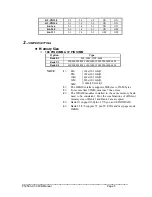
  Special Function Jumpers

Jumper Number

FUNCTION

J1

K/B  CONNECTOR

J2

PS/2  MOUSE

J6

IR

COM  1

COM  PORT  1

COM  2

COM  PORT  2

IDE  1

IDE  1

IDE  2

IDE  2

FDC  1

FDD

LPT  1

PRINT  PORT  1

JP4

CMOS  CLEAR

J7

MULTIFUNCTION  CONNECTOR


l


  Multifunction Connector

Power LED/Key Lock

Speaker

Turbo

LED

Ext_SMI

HDD

LED

Reset

Green
LED

+

+

+ + + + +

Summary of Contents for P5V580-AT-C

Page 1: ..._____________________________________________________________ P5V580 AT C M B Manual Page 1 P5V580 AT C ISA PCI IO Mother Board User s Manual PART NO M523G0010C Rev 1 0 AUG 1997...

Page 2: ...pers 5 2 2 Chart of Jumper 6 3 AWARD BIOS SETUP 7 3 1 Entering Setup 7 3 2 The Main Menu 8 3 3 Standard CMOS Setup Menu 10 3 4 BIOS Features Setup Menu 13 3 5 Chipset Features Setup Menu 16 3 6 Power...

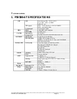
Page 3: ...m 8M up to 256M Bytes DRAM Module SIMM x 4 for 2 Banks of 72 Pin DIMM x 1 of 168 Pin for 3 3V Sync and EDO DRAM Data Path 64 Bit Wide On Board I O I O Function Local Bus Enchanced Dual Channel IDE Bus...

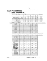
Page 4: ...75MHz 2 3 2 3 2 3 OFF OFF 90MHz OFF OFF 120MHz 2 3 2 3 1 2 OFF ON 150MHz ON ON 100MHz OFF OFF 133MHz OFF ON 166MHz 2 3 1 2 2 3 ON ON 200MHz ON OFF 233MHz OFF OFF If select Cyrix CPU JP10 must be set O...

Page 5: ...16M 16M 32M 32M 64M 64M Bank4 5 4M 4M 8M 8M 16M 16M 32M 32M 64M 64M NOTE 1 4M 1Mx 32 36 bit 2 8M 2Mx 32 36 bit 2 16M 4Mx 32 36 bit 2 32M 8Mx 32 36 bit 2 64M 16Mx 32 36 bit 2 2 The DRAM interface suppo...

Page 6: ...Special Function Jumpers Jumper Number FUNCTION J1 K B CONNECTOR J2 PS 2 MOUSE J6 IR COM 1 COM PORT 1 COM 2 COM PORT 2 IDE 1 IDE 1 IDE 2 IDE 2 FDC 1 FDD LPT 1 PRINT PORT 1 JP4 CMOS CLEAR J7 MULTIFUNC...

Page 7: ...Page 7 2 JUMPER SETTING 2 2 Chart of jumper JUMPER OUTLINE VT 82C587VP VT 82C587VP 64KX32 64KX32 SMC669 VT 82C586VP PCI1 PCI2 PCI3 VT 82C585VP JP5 6 7 8 J7 BIOS JP4 SL1 SL2 SL3 SL4 LPT1 BANK5 BANK4 B...

Page 8: ...the POST Power On Self Test press Del key or simultaneously press Ctrl Alt and Esc keys TO ENTER SETUP BEFORE BOOT PRESS CTRL ALT ESC OR DEL KEY If the message disappears before you respond restart th...

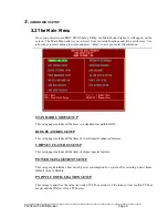
Page 9: ...b menu STANDARD CMOS SETUP This setup page includes all the items in a standard compatible BIOS BIOS FEATURES SETUP This setup page includes all the items of Award special enhanced features CHIPSET FE...

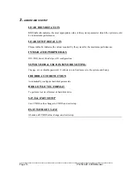
Page 10: ...alues required by the system for the maximum performance INTEGRATED PERIPHERALS IDE FDD Serial Parallel port I O configuration SUPERVISOR USER PASSWORD SETTING Change set or disable password It allows...

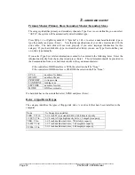
Page 11: ...em and then use the PgUp or PgDn keys to select the value you want in each item Date The date format is day date month year day The day of week from Sun to Sat determined by the BIOS is read only date...

Page 12: ...the information directly from the keyboard and press Enter This information should be provided in the documentation from your hard disk vendor or the system manufacturer If the controller of HDD inter...

Page 13: ...t Keyboard The system boot will not stop for a keyboard error it will stop for all other errors All But Diskette The system boot will not stop for a disk error it will stop for all other errors All Bu...

Page 14: ...locate the problem WARNING Disk boot sector is to be modified Type Y to accept write or N to abort write Award Software Inc Enabled Activates automatically when the system boots up causing a warning m...

Page 15: ...CDROM C A 9 SCSI C A 5 D A SCSI 10 C only Swap Floppy Drive This category can change A and B drive Enabled Assign A to B B to A drive Disabled Normal Boot Up Floppy Seek During POST BIOS will determin...

Page 16: ...msec 500 500 msec 750 750 msec 1000 1000 msec Security Option This category allows you to limit access to the system and Setup or just to Setup System The system will not boot and access to Setup will...

Page 17: ...This option specifies Turbo Fast Medium Normal mode DRAM Timing Video BIOS Cacheable The Video BIOS Cache selection allows you to cache the video BIOS for even higher performance The default setting...

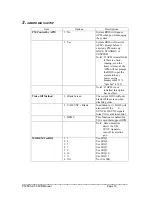
Page 18: ...omsumed Default value is Disable The following pages tell you the options of each item describe the meanings of each option Item Options Descriptions Power Management 1 Disable Global Power Management...

Page 19: ...mpt the BIOS to put the system into any power saving modesymbol 33 f Symbol s 10 5 Note2 If APM is not installed this option has no effect Video Off Method 1 Blank Screen The system BIOS will only bla...

Page 20: ...ode Remark 1 1 Disable System will never enter SUSPEND mode 2 1 Min 2 Min 4 Min 6 Min 8 Min 10 Min 20 Min 30 Min 40 Min 1 Hr Defines the continuous idle time before the system enters SUSPEND mode If a...

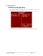
Page 21: ...e 21 3 AWARD BIOS SETUP 3 7 PNP PCI Configuration Setup You can manually configurate the PCI Device s IRQ The following pages tell you the options of each item describe the meanings of each option The...

Page 22: ...r PCI IDE devices determine the location of the PCI IDE device See below item PCI SLOT1 PCI SLOT2 PCI SLOT3 PCI SLOT4 symbol 45 f Symbol s 10 5 assign IRQ 14 for primary IDE INT IRQ 15 for secondary I...

Page 23: ...E primary master HDD PIO Mode IDE Primary Master UDMA This option selected the on board PCI IDE primary master HDD Ultra DMA Mode IDE Primary Slave PIO This option selected the on board PCI IDE primar...

Page 24: ...Mode Onboard FDC Controller This option enables Onboard FDC controller or disabled Onboard FDC controller and use expand FDC controller card Onboard COM Port 1 This option specifies the first serial...

Page 25: ...password from CMOS memory You will be asked to confirm the password Type the password again and press Enter You may also press Esc to abort the selection and not enter a password To disable password...

Page 26: ...ROM PCI ISA BOPS 2A59GE3A CMOS SETUP UTILITY AWARD SOFTWARE INC HARD DISKS TYPE SIZE CYLS HEAD PRECOMP LANDZ SECTOR MODE Primary Master Select Primary Master Option N Skip N OPTION SIZE CYLS HEADS PRE...

Page 27: ...accessing the IDE controller will transform the logical address described by sector head cylinder number into its own physical address inside the HDD The maximum HDD size supported by LBA mode is 8 4...

Page 28: ...32 x no Sector 63 x bytes per sector 512 1 Gigabytes 3 Remarks To support LBA or LARGE BLOCK mode of HDDs there must be some sofewares involved All these software is located in the Award HDD Service...

Page 29: ...all the changes to the CMOS values and the system cannot boot with the CMOS values selected in Setup restart the system by turning it OFF then ON or Pressing the RESET button on the system case You m...

Page 30: ...TERY HAS FAILED CMOS battery is no longer functional It should be replaced CMOS CHECKSUM ERROR Checksum of CMOS is incorrect This can indicate that CMOS has become corrupt This error may have been cau...

Page 31: ...ialize the keyboard Make sure the keyboard is attached correctly and no keys are being pressed during the boot Manufacturing POST loop System will repeat POST procedure infinitely while the P15 of key...

Reviews: