background image

Viking 3 Manual

P5MVP3-AT

Page 22

AWARD BIOS SETUP                                                               

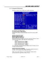
Onboard COM Port 1 (3F8/IRQ4)
Onboard COM Port 2 (2F8/IRQ3)

These options allow you to specify the input/output addresses and IRQs for the
serial ports.  You can also choose to disable them as well.

Onboard COM Port 2 Mode (Standard)

This function allows you to specify the COM Port 2 operation mode as Standard,
HPSIR or ASKIR.

IDE HDD Black Mode (Disabled)

This feature enhances hard drive performance by making multi-sector transfer
instead of one sector per transfer.  Most IDE hard drives, except early designs,
support this feature.

Onboard Print Port (378)

This option allows you to specify the input/output address of your printer port
(LPT1).  You can also choose to disable the printer port.

Onboard Print Port Mode (Normal)

This feature lets you select which mode the printer port will operate in:

Normal

Standard and Bi-Directional Printer Port

EPP

Enhanced Printer Port

ECP

Extended Printer Port

Normal mode is the IBM AT and PS/2 compatible mode.  EPP mode enhances
the printer port’s throughput by directly writing/reading data to/from the printer
port with latch.  ECP mode supports DMA and RLE (Run Length Encoded)
compression and decompression.

4.11 Supervisor and User Password

You can use these two options to set the supervisor password (restricts access
to the Award BIOS Setup) and the user password (restricts access to the
system).  Once you have entered the password the system will prompt you to re-
enter the password to confirm the selection.

NOTE:  If you have forgotten your password, you can clear the CMOS (refer to
the Special Jumpers Chart) which will clear all user-defined settings and
passwords in the BIOS.

Summary of Contents for Viking 3

Page 1: ...Viking 3 P5MVP3 AT AGP PCI ISA I O Motherboard User s Manual PART NUMBER M556G00300 Rev 1 0JUNE 1998...

Page 2: ...Function Jumpers 7 3 5 Power Supply 8 3 6 Multifunction Connector 8 3 7 Memory Size 8 3 8 Jumper Layout Chart 9 4 AWARD BIOS SETUP 10 4 1 Entering Setup 10 4 2 Main Menu 10 4 3 Standard CMOS Setup 11...

Page 3: ...of 168 Pin for Sync DRAM 3 3V Non Buffer or 3 3V EDO Data Path 64 Bit Wide On Board I O I O Function Local Bus Enchanced Dual Channel IDE Bus Master PCI IDE Mode 4 Support Ultra DMA 33 Mode Supports E...

Page 4: ...re working on the interior of the computer 2 Hold the motherboard peripherals and components by the edges and try not to touch the IC chips leads and circuitry 3 If possible use a grounded wrist strap...

Page 5: ...Mounting the Motherboard Line up the keyboard connector on the motherboard with the keyboard hole on the case This should also help you in lining up the mounting holes on the motherboard Then use scre...

Page 6: ...ve or other IDE device is set correctly You may need to refer to your hard drive or other IDE device s documentation to identify the correct jumper settings Serial Ports Interface COM 1 COM 2 Parallel...

Page 7: ...66MHz 2 2 3 1 2 1 2 166MHz 66MHz 1 2 2 3 2 3 2 5 2 3 2 3 1 2 200MHz 66MHz 3 1 2 2 3 1 2 233MHz 66MHz 3 5 1 2 1 2 1 2 Cyrix JP7 JP8 JP9 JP4 JP5 JP6 6x86 P150 60MHz Bus 2x 2 3 2 3 2 3 2 3 1 2 1 2 6x86MX...

Page 8: ...2 266 66MHz 1 2 2 3 2 3 4 2 3 2 3 1 2 K6 2 300 100MHz 1 2 1 2 1 2 3 1 2 2 3 1 2 3 3 SDRAM Clock Settings SDRAM CLOCK JP10 SAME AS CPU 2 3 SAME AS AGP 1 2 3 4 Special Function Jumpers Jumper Number FU...

Page 9: ...ED GREEN LED 1 2 20 19 NOTE Black pins on diagram identify positive current pins 3 7 Memory Size Option TYPE DIMM1 2 3 8M 16M 32M 64M 128M 256M NOTE The P5MVP3 AT only supports 168 pin DIMM modules DR...

Page 10: ...hart AT PWR CON ATX PWR CON PS 2 MOUSE PCI1 PCI2 PCI3 PCI4 ISA1 ISA2 ISA3 SOCKET 7 BAT1 IDE1 IDE2 COM2 COM1 K B FDD LPT1 JP4 JP5 JP6 DIMM1 DIMM2 DIMM3 AGP BIOS SMC669 J1 JP3 A B C D FAN 2 VIA VT82C586...

Page 11: ...BOOT PRESS CTRL ALT ESC OR DEL KEY If the message is no longer displayed before you respond then just restart your system by turning the power off and then back on again You may also restart your sys...

Page 12: ...aults for the BIOS Load Setup Defaults will load the factory defaults for the Setup Utility Integrated Peripherals includes configuration options for the on board IDE Controllers Floppy Drive Controll...

Page 13: ...a different color from the rest of the text on your screen To receive help on a highlighted item just press the F1 key to bring up the help menu The memory display at the lower right corner of the scr...

Page 14: ...landing zone SECTOR number of sectors and MODE The SIZE field will automatically adjust according to the configuration you specify in the other fields Your hard drive s documentation should provide yo...

Page 15: ...ve against accidental modifications Any attempt to write to them will cause the system to halt and display a warning message If this occurs you can either allow the operation to continue or use a boot...

Page 16: ...terval for displaying the first and second characters of repeated keystrokes You can choose from 250ms 500ms 750ms and 1000ms Security Option Setup Determines when the system prompts for a password if...

Page 17: ...o BIOS execution System BIOS Cacheable Disabled Enabling this function allows you to cache the system BIOS to help enhance system performance Memory Hold at 15MB Addr Disabled Enabling this function m...

Page 18: ...is for compatibility testing CPU Warning Temperature Disabled Enabling this function will allow the system to slow down when the CPU temperature is over the warning threshold Current CPU System Temper...

Page 19: ...states one is suspend mode and the other is Soft Off mode Pushing the power button for less than 4 seconds places the system into suspend mode When the power button is pressed for more than 4 seconds...

Page 20: ...these devices HDD FDD ON This functions monitors the floppy and hard drives Setting the value to NO will resume the system from Doze mode or Standby mode if any activity is detected from those devices...

Page 21: ...e Enables or disables ACPI I O devices PCI Delay Activated By Level Specifies to the chipset whether IRQ signal input is a Level or an Edge trigger Assign IRQ for USB Enabled When set to DISABLED the...

Page 22: ...function The PIO mode specifies the data transfer rate of the hard drive Examples Mode 0 data transfer rate is 3 3MB sec Mode 1 data transfer rate is 5 2MB sec Mode 2 data transfer rate is 8 3MB sec...

Page 23: ...ort Onboard Print Port Mode Normal This feature lets you select which mode the printer port will operate in Normal Standard and Bi Directional Printer Port EPP Enhanced Printer Port ECP Extended Print...

Page 24: ...setting and will put the drive into LBA mode if supported by the drive This option is generally recommended for most applications Pressing the N key will instead skip to the next drive Once the auto...

Page 25: ...ou change your motherboard s chipset My system has all the necessary components installed but I cannot get a display on my monitor If you have a speaker connected to your motherboard then listen for b...

Page 26: ...3 Short repeats Video card not installed or bad One Long 2 Short Repeats BIOS bad Repetitive Short Beeps Keyboard not detected Error Messages CHECKSUM ERROR BIOS DEFAULTS LOADED Either bad battery or...

Reviews: