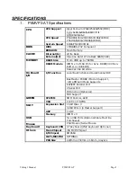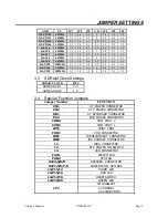
Viking 3 Manual
P5MVP3-AT
Page 5
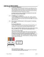
INSTALLATION GUIDE
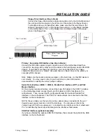
Floppy Drive Interface (34-pin block)
Connect the floppy ribbon cable’s single connection end to the motherboard and
then connect the two plugs on the other end of the cable to the floppy drive(s).
To identify which way to install the cable, make sure that the red stripe on the
cable is connected to pin 1 on the floppy drive and pin 1 on the floppy interface
on the motherboard. Pin 1 on the floppy drive is located closest to the power
pins on the floppy drive.
Primary / Secondary IDE Interface (two 40-pin blocks)
Connect the IDE ribbon cable’s single connection end to the motherboard and then
connect the two plugs at the other end of the cable to the hard drive(s) and/or CD-ROM
drive(s). If you have more than one hard drive, you can connect them in a “daisy-
chained” manner (one as a “master” drive and one as a “slave” drive on the primary or
secondary IDE channel).
Note: Make sure the master and slave jumpers on the hard drive or other IDE device is
set correctly. You may need to refer to your hard drive or other IDE device’s
documentation to identify the correct jumper settings.
Serial Ports Interface (COM 1 / COM 2), Parallel Port Interface (LPT1) and PS/2
Mouse Interface
On the provided serial port cables, connect the 9-pin Port cable to the COM 1 interface
on the motherboard and connect the 25-pin Port cable to COM 2 interface on the
motherboard. Then connect the 25-pin female Parallel Port cable to Parallel Port
interface on the motherboard. The PS/2 Port cable will also be connected to the PS/2
interface on the motherboard.
NOTE: Please make sure the red strip on the cable is always connected to the pin 1
(toward power supply socket) on all of the interfaces. You can always refer to the
Jumper Layout Chart to see where pin 1 is located for any interface on the motherboard.
Pin 1 is identified by the small, white triangle in the interfaces themselves.
USB Port Interface (optional assembly)
If you have obtained the optional USB Port Interface, then connect the cable to the USB
interface on the motherboard.
Pin 1
Floppy
Drive
FDD Ribbon Cable
Pin 1 (red dot)
Floppy Cable Connection
Diagram


