background image

Schmid & Wezel
D75433 Maulbronn, 

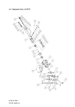
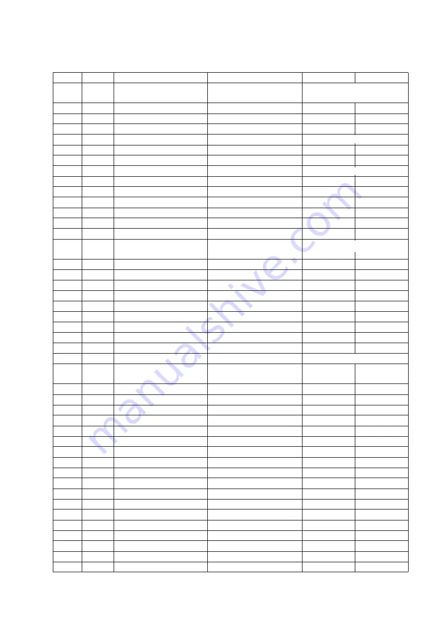
A.3 List of Spare Parts and Wear Parts

Z079

Z080

Figur
e no.

Piece

Designation

Order no.

Hook cutter

008 009 556

008 009 711

1

1

Housing, complete

007 009 558

007 009 710

2

1

Piston rod, complete

007 009 566

007 009 566

3

2

Fork, complete

007 009 567

007 009 567

4

1

Bolt

003 009 571

003 009 571

4a

3

Locking ring

001 317 912

001 317 912

5

1

Cutter body, complete

003 009 557

003 009 557

6

2

Plug

001 368 644

001 368 644

6a

2

Thread

001 368 643

001 368 643

7

1

Guide, complete

007 009 564

007 009 564

8

1

Threaded ring

003 009 563

003 009 563

9

1

Ring

001 607 121

001 607 121

10

1

O-ring

001 312 695

001 312 695

11

1

Piston, complete 
(including 11a -14)

007 006 721

007 060 721

11a

1

Piston

003 006 391

003 006 391

12

1

Piston guide ring

001 607 122

001 607 122

13

1

O-ring

001 312 694

001 312 694

14

1

Ring

001 607 120

001 607 120

15

2

Blade, complete

007 009 568

007 009 568

16

2

Bolt

003 009 570

003 009 570

17

1 pair

Tensioning device

003 009 572

003 009 572

18

1

Stud bolt

003 009 569

003 009 569

19

1

Hexagon nut

001 304 505

001 304 505

20

1

Holder

21

2

Flat-head screw with 
hexagon socket

001 326 508

001 326 508

22

1

Conical spring

003 001 445

003 001 445

23

1

Valve bolt, complete

007 009 561

007 009 561

24

1

O-ring

001 312 697

001 312 697

25

1

Washer

003 007 485

003 007 485

26

1

Locking ring

001 312 308

001 312 308

27

1

Valve arm

003 001 575

---

27a

1

Valve lever, complete

---

007 0

14


364

28

1

Straight pin

001 306 418

001 306 418

29

1

Bracket, complete

007 006 386

---

29a

1

Suspension

---

003 009 001

30

2

Split washer

001 317 007

---

30 a

1

Handle

---

003 008 998

31

2

Hex head screw

001 325 911

---

31a

4

Setscrew

---

001 326 306

32

1

Seal ring

001 314 306

001 314 306

33

2

Threaded nipple

001 367 105

001 367 105

34

1

Seal ring

001 314 308

001 314 308

35

2

Threaded nipple

001 367 106

001 367 106

               007 011 419

007 011 418 

007 011 418 

003 011 419

003 011 419

             007 010 260

007 010 578     003 014 367

003 006 455

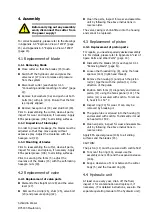
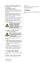
Summary of Contents for Z079

Page 1: ...m Bedienpersonal aush ndigen Important Informations Please forward these operating instructions to your operating personell Betriebsanleitung Operating instructions Wartungsanleitung Maintenance instr...

Page 2: ...Messerwechsel 6 4 2 Ventilwechsel 6 4 3 Kolbenwechsel 6 4 4 Hydraulikaggregat 6 4 5 Einstellung des Federzuges 7 5 Instandhaltung 7 6 Reinigung und Wartung 9 6 1 T gliche Reinigung nach Beendigung der...

Page 3: ...te aus Ver schlei gr nden vermieden werden Die Zange ist geeignet f r Abtrenn und Zerlege arbeiten in Mittel und Gro betrieben sowohl f r die Fleisch als auch f r die Gefl gelindustrie Die Maschine is...

Page 4: ...ordnung kann Unf lle zur Folge haben 2 Ber cksichtigen Sie Umgebungseinfl sse Sor gen Sie f r gute Beleuchtung min 500 Lux 3 Halten Sie andere Personen von Ihrem Arbeits platz fern Arbeiten Sie konzen...

Page 5: ...zu verwendenden Hydraulikschl uche haben unterschiedlich gro e Gewindeanschl sse und k nnen daher nicht falsch angeschlossen werden Die Zerlegezange nur ausgeschal tet an das Betriebsnetz anschlie en...

Page 6: ...der beidseitig mon tierbare Halter 20 der Zange beim Schneidevor gang auf der Seite der materialhaltenden Hand d h f r Linksh nder rechts und f r Rechtsh nder links montiert sein siehe Abb 3 Abbildun...

Page 7: ...ren Sicherungsring 26 Scheibe 25 Ventilbol Vor allen Montagearbeiten das Ger t vom Betriebsnetz trennen zen 23 und Druckfeder 22 abnehmen Teile reinigen auf Verschlei pr fen und in umgekehrter Reihenf...

Page 8: ...trisches Aggregat D druckluftge steuertes Aggregat St rung m gliche Ursache Behebung D Bei Bet tigung der Ventilhebel 27 l uft Pumpe nicht 1 Druckluftversorgung unter brochen Druckluftversorgung berpr...

Page 9: ...Anschluss des R ck laufschlauches 11 Defekte Dichtungen Teile 9 10 13 und 14 Dichtungen austauschen 12 Messer 15 verklemmt siehe Kapitel 4 1 Messerwech sel S 6 13 lstand zu gering l nachf llen siehe K...

Page 10: ...3 04 06 40554 D sseldorf Vor allen Reinigungs und War tungsarbeiten das Ger t vom Be triebsnetz trennen Keine scharfen L sungsmittel zu setzen Keinen Dampf bzw Hochdruckstrahler verwenden Ger t nicht...

Page 11: ...en nur von Fachkr ften vorge nommen werden F r Reparaturen steht Ihnen unsere Serviceab teilung zur Verf gung Bitte wenden Sie sich im Falle einer Reparatur an die n chstgelegene Vertragswerkstatt ode...

Page 12: ...Schmid Wezel D 75433 Maulbronn A Anhang A 1 Massskizze...

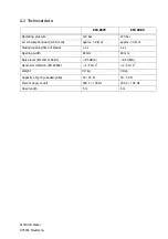
Page 13: ...a 30 l Schnitt ca 30 l Schnitt Schlie zeit ffnungszeit der Zangen 1 2 s 1 2 s Zangen ffnung 80 mm 80 mm Schalldruckpegel EN ISO 11688 1 85 dB A 85 dB A Hand Arm Vibration EN 28662 2 5 m s2 2 5 m s2 Ge...

Page 14: ...003 009 570 003 009 570 17 1 Paar Spannteil 003 009 572 003 009 572 18 1 Gewindebolzen 003 009 569 003 009 569 19 1 Sechskantmutter 001 304 505 001 304 505 20 1 Halter 21 2 Senkschraube mit I Skt 001...

Page 15: ...schlauch 001 606 582 001 606 582 41 10 Kabelbinder 001 371 913 001 371 913 Sonderzubeh r 133 1 Hydraulik l 001 365 614 001 365 614 134 1 Federzug 001 620 036 001 620 036 135 1 Spezial l 5 l f r Wartun...

Page 16: ...Schmid Wezel D 75433 Maulbronn A 4 Explosionszeichnung Z079...

Page 17: ...Schmid Wezel D 75433 Maulbronn A 5 Explosionszeichnung Z080...

Page 18: ...Schmid Wezel D 75433 Maulbronn...

Page 19: ...Schmid Wezel D 75433 Maulbronn A 6 Explosionszeichnung Schlaucheinheit...

Page 20: ...ng instructions to your operating personell Wichtige Informationen Diese Anleitung unbedingt dem Bedienpersonal aush ndigen Operating instructions Betriebsanleitung Maintenance instructions Wartungsan...

Page 21: ...ement of blade 6 4 2 Replacement of valve 6 4 3 Replacement of piston 6 4 4 Hydraulic unit 6 4 5 Adjustment of spring loaded pulley 7 5 Maintenance 7 6 Cleaning and maintenance 9 6 1 Daily cleaning at...

Page 22: ...ge from excessive wear It is suitable for cutting and breaking in large and medium sized meat and poultry processing plants The machine is not designed for any other use If you wish to use the equipme...

Page 23: ...properly illuminated min 500 lux 3 Prevent unauthorised persons from accessing your workplace Concentrate on your work and use common sense Do not handle the hook cutter if you feel tired and or find...

Page 24: ...The hydraulic hoses supplied with the unit have threaded connectors of different diameter so that lines cannot be confused 3 1 3 Connecting and disconnecting of cutter The cutter is equipped with a p...

Page 25: ...umber of cuts have been completed For safety reasons the holder of the cutter 20 that can be mounted on either side must be mounted on the side of the hand that holds the material For left handed pers...

Page 26: ...ut any assembly work disconnect the cutter from the power supply Clean the parts inspect for wear and assemble unit by following the above instructions in reverse order The valve casing is shrink fitt...

Page 27: ...1 Compressed air supply blocked or defective Check compressed air system 2 Pressure reducer incorrectly set Adjust pressure 6 bar at the pressure reducer 3 Water trap or oiler defective Inspect oiler...

Page 28: ...de page 6 13 Hydraulic fluid level too low Refill fluid see chapter 6 3 1 Hydraulic unit page 9 Valve bolt 23 is not operated when the valve lever 27 is pressed 14 Valve bolt is defective Replace valv...

Page 29: ...k disconnect the cutter from the power supply Do not use aggressive detergents Do not clean with steam or high pressure water jet Do not immerse cutter in water compliance with the applicable hygiene...

Page 30: ...completed by specialist technicians S W operates an extensive after sales service network Contact your local authorized repair shop or the Schmid Wezel customer service department for more informatio...

Page 31: ...Schmid Wezel D75433 Maulbronn A Appendix A 1 Dimension Drawing...

Page 32: ...approx 30 l cut approx 30 l cut Closing opening time of blades 1 2 s 1 2 s Opening width 80 mm 80 mm Noise level EN ISO 11688 1 85 dB A 85 dB A Hand arm vibration EN 28662 2 5 m s2 2 5 m s2 Weight 4...

Page 33: ...2 Blade complete 007 009 568 007 009 568 16 2 Bolt 003 009 570 003 009 570 17 1 pair Tensioning device 003 009 572 003 009 572 18 1 Stud bolt 003 009 569 003 009 569 19 1 Hexagon nut 001 304 505 001...

Page 34: ...118 001 607 118 40 1 High pressure hose 001 606 582 001 606 582 41 10 Cable tie 001 371 913 001 371 913 Extras 133 1 Hydraulic fluid 001 365 614 001 365 614 134 1 Spring loaded pulley 001 620 036 001...

Page 35: ...Schmid Wezel D75433 Maulbronn A 4 Exploded View of Z079...

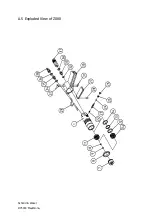
Page 36: ...Schmid Wezel D75433 Maulbronn A 5 Exploded View of Z080...

Page 37: ...Schmid Wezel D75433 Maulbronn...

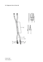
Page 38: ...Schmid Wezel D75433 Maulbronn A 6 Explosion View of hose kit...

Page 39: ......

Page 40: ......

Reviews: