9
en
GB
F
D
E
NL
P
GR
TR
CZ
SK
RUS
UK
PL
H
LV
EST
LT
RO
supplied wrench.
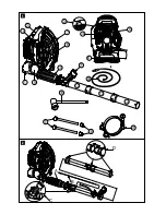
3. Fit the control handle (11, Fig.1) on the
blower tube (12, Fig.1) after fully undoing
the screw located under the locking lever
(Fig.5) using the supplied hex wrench.
Refer to Fig.4:
1. With the locking lever in its lowered
position (locked), tighten the screw
sufficiently to secure the control handle to
the blower tube but without tightening it
fully. Do not tighten the screw with the
lever in the open position.
2. Wind the antistatic cable around the blower
tube in a spiral (B, Fig.2) and insert it into the
hole in the blower tube; connect the end of
the antistatic cable B to the terminal in the
control handle (as shown in circle C, Fig.2).
3. Couple the blower tubes (13-14, Fig.1)
by means of the bayonet fitting (see the
bayonet fitting in the enlarged view in circle
D, Fig.2).
Adjusting the control handle
Correct positioning of the control handle
is extremely important in order to work
comfortably with the blower. To adjust the
control handle position:
1. Raise the locking lever (1, Fig.5).
2. Find the most comfortable working position
by sliding the control handle and adjusting
its angle.
3. When you find the preferred position, lock
the control handle by lowering the locking
lever.
Adjusting the harness and quick release
WARNING - The harness must be
adjusted with the engine stopped.
Before using the blower it is extremely
important to ensure the weight of the machine
is correctly balanced on your shoulders. This is
done by adjusting the length of the shoulder
straps until the machine is perfectly in contact
with your back and shoulders.
Note that correct balancing of the machine
is especially important when working on
gradients. To tighten the shoulder straps pull as
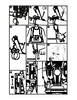
shown in Fig.7.
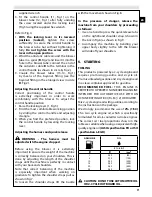
To loosen the shoulder straps lift the buckle
with the movement shown in Fig.8.
In the presence of danger, release the
machine from your shoulders by proceeding
as follows:
1. Use one hand to press the quick release tabs
on the right-hand shoulder strap (shown in
the box in Fig.6) as shown in Fig.9.
2. Accompany the machine by bending your
upper body slightly to the left: the blower
will slide off your shoulders.
5. STARTING
FUELING
This product is powered by a 2-cycle engine and
requires pre-mixing gasoline and 2-cycle oil.
Pre-mix unleaded gasoline and 2-cycle engine oil
in a clean container approved for gasoline.
RECOMMENDED FUEL: THIS ENGINE IS
CERTIFIED TO OPERATE ON UNLEADED GASOLINE
INTENDED FOR AUTOMOTIVE USE WITH AN
OCTANE RATING OF 89 ([R + M] / 2) OR HIGHER.
Mix 2-cycle engine oil with gasoline according to
the instructions on the package.
We strongly recommend the use of 2% (1:50)
Efco two cycle engine oil, which is specifically
formulated for all air-cooled two-stroke engines.
The correct oil / fuel proportions shown in the
table are suitable when using an equivalent high-
quality engine oil (JASO specification FD or ISO
specification L-EGD).
CAUTION: DO NOT USE AUTOMOTIVE OIL
OR 2-CYCLE OUTBOARD OIL.
GASOLINE
OIL
2% - 50:1
ℓ
ℓ
(cm
3
)
1
5
10
15
20
25
0,02
0,10
0,20
0,30
0,40
0,50
(20)
(100)
(200)
(300)
(400)
(500)
Summary of Contents for SA 9500
Page 2: ...English 5 Fran ais 20 Espa ol 36...
Page 3: ...1 3 2 11 10 9 12 13 14 7 8 15 4 5 6 16 17 18 19 20 D C A B 1 2...
Page 4: ...OK 1 3 4 6 8 12 5 11 7 9 A B...
Page 5: ...1 2 3 4 RCJ6Y 0 5 mm 0 020 13 15 17 18 19 14 16 4 3 2 1 5...
Page 6: ......
Page 54: ......
Page 55: ......


