background image

Daily

Document ID: OMM-00144-L

VUTEk 3r & 5r Series Maintenance Guide

35

The following maintenance tasks must be performed once daily.

PPE Items:

GLOVES NITRILE DISPOSABLE BOX LARGE 
SAFETY GLASSES 

Required Items:

WIPES 9X9 CLEAN ROOM

How-to Video:


Directions:

NOTE:  Even if you are not using the white ink system, you must Purge the two white INK CHANNELS, stir the ink

channels, operate the mixer in the white Main Ink Tank, and perform a 2 second purge on both white ink
channels at least once a day.

NOTE:  Print a small WHITE print job at least once a day to maintain the print head quality.

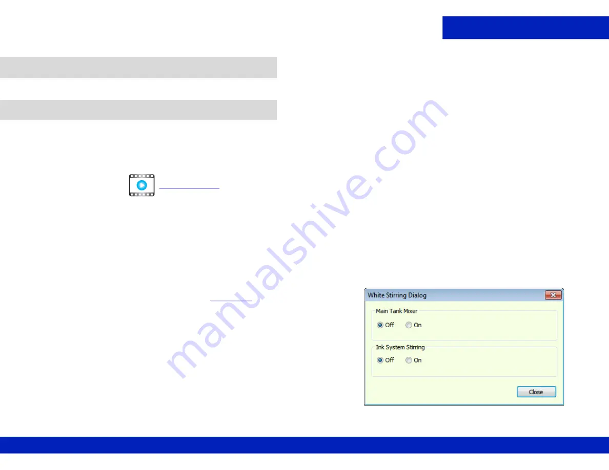
1.

Open the 

Tools

 tab and select the 

White Stirring

 option. The 

White Stirring 

dialog box opens, 

Figure 5-1

2.

Click the 

Main Tank Mixer 

and the 

Ink System Stirring


ON 

radio 

buttons and click 

Close

.

3.

Wait for two minutes and re-open the 

White Stirring Dialog

 and 

click the 

Main Tank Mixer 

and the 

Ink System Stirring


OFF 

radio 

buttons and click 

Close

.

4.

Perform a 2 second Purge on White Channels only. 

5.

Dry wipe the White print head faces, allowing the wipe to absorb 

excess ink from the print heads.

6.

To make the White Stirring option automatic, open the 

PRERENCES 

dialog box.

5.0

Once Daily Maintenance

5.1

Perform white ink maintenance.

CLICK TO PLAY

Figure 5-1  White Stirring Dialog

Summary of Contents for VUTEk 3r Series

Page 1: ...Maintenance Guide VUTEk3r 5r Series Digital Inkjet Printer ...

Page 2: ...215 562 6 219 155 6 219 659 6 222 641 6 224 048 6 225 974 6 226 419 6 238 105 6 239 895 6 256 108 6 269 190 6 271 937 6 278 901 6 279 009 6 289 122 6 292 270 6 299 063 6 310 697 6 321 133 6 327 047 6 327 050 6 327 052 6 330 071 6 330 363 6 331 899 6 337 746 6 340 975 6 341 017 6 341 018 6 341 307 6 347 256 6 348 978 6 356 359 6 366 918 6 369 895 6 381 036 6 400 443 6 429 949 6 449 393 6 457 823 6 ...

Page 3: ... with Jet Surface Cleaner part 45119466 and not IPA Small text edits to pgs 37 and 38 DR 5165 DR 5119 F 08 13 2018 Changes to 4hr routines and Print Head Cleaning routine Added additional Common Mainte nance Items DR 5194 G 10 04 2018 Added printer model to top of Maintenance Log Removed contact table and instruction text from Log DR 5304 H 02 14 2019 Added Apply print head cleaning solution to th...

Page 4: ...onizer bars 31 4 7 Clean the carriage crash sensors sides 32 4 8 Perform print head care 33 5 0 ONCE DAILY MAINTENANCE 35 5 1 Perform white ink maintenance 35 6 0 EVERY 40 HOURS 38 6 1 Clean the free fall rollers 38 6 2 Clean the T Tension rubber roller 39 6 3 Clean the Y Shaft rubber roller 40 6 4 Clean metal input feed press and collector rollers 41 6 5 Lubricate the carriage bearings 43 6 6 Che...

Page 5: ...Introduction Document ID OMM 00144 L VUTEk 3r 5r Series Maintenance Guide 5 1 0 Introduction Maintenance Guide ...

Page 6: ... inkjet support efi com For more information on EFI and it s products visit www efi com Before performing any scheduled maintenance procedure operators are required to complete Operator Certification Training For more information visit https inkjet support efi com training Ensure all required items are on hand before beginning any maintenance procedure Required items can be found in the Required I...

Page 7: ...ted as follows WARNING Comments in a red highlighted box with triangle symbol Used when failure to follow will result in operator injury or printer damage Example CAUTION Comments in a yellow highlighted box Used when failure to follow could result in operator injury or printer damage Example NOTE Comments in italics Used when failure to follow could result in printer errors Used when describing h...

Page 8: ...t the retaining pins into the LH and RH pin sockets 3 Ensure the retaining pins are inserted fully into the sockets and proceed with any required maintenance tasks 4 Remove the retaining pins after completing tasks 1 4 Using Retaining Pins Warning The Printer Hood represents a CRUSHING hazard when open To prevent Operator injury always install the Retaining Pins when the Printer Hood is open while...

Page 9: ...enance Guide 9 A series of Maintenance Videos is available for users to review prior to completing any maintenance procedure Each procedure contains a link to review the related maintenance video 1 5 Maintenance Videos CLICK TO PLAY Figure 1 3 Example video link ...

Page 10: ...0 1 650 357 4790 EuroInk efi com Canada Mexico South America 1 650 357 4790 Technical Support https inkjet support efi com US Canada 855 EFI 4HLP 855 334 4457 32 2 749 94 50 65 6221 2765 Mexico South America 1 412 690 4321 DE 49 2102 745 4500 NL 31 20 658 8080 8069 UK 44 12462 98085 Order Parts US Inkjet Orders efi com EuroParts efi com InternationalOrders efi com Canada Mexico South America Inter...

Page 11: ...current date and time if applicable and write your initials in the space provided Please retain copies of the Maintenance Log Field Engineers will often ask to review your maintenance records during service visits The Printer Beam contains powerful magnets that assist the carriage movement Persons with implanted medical devices must take extreme caution to avoid being within or contacting these ma...

Page 12: ...ter 15 minutes Seek medical attention Ingestion Do not induce vomiting drink two glasses of water Seek medical attention Skin contact Remove contaminated clothing Flush with plenty of cool water and non abrasive soap Seek medical attention if irritation develops Inhalation Move person to fresh air Seek medical attention if symptoms develop 1 11 First Aid Inks and Solvents ...

Page 13: ...Introduction Document ID OMM 00144 L VUTEk 3r 5r Series Maintenance Guide 13 2 0 Scheduled Maintenance Maintenance Guide ...

Page 14: ...er we provide a Maintenance Log which makes tracking routine maintenance easy The Maintenance Log provides you with a list of preventative maintenance tasks as well as the means for tracking the completion of each task Please keep your maintenance log up to date Your EFI Service Engineer will review your maintenance log during scheduled visits The maintenance guidelines are based on an eight hour ...

Page 15: ...Introduction Document ID OMM 00144 L VUTEk 3r 5r Series Maintenance Guide 15 3 0 Every 4 Hours Maintenance Guide ...

Page 16: ...s NOTE Before wiping the print heads clean any accumulated ink residue around the print head area and the bottom of the carriage print head plate This procedure should be carried out daily at minimum or if needed every 4 hours of production 1 Raise the carriage to its highest position 2 Open the printer hood and insert the retaining pins into the LH and RH pin sockets 3 Wipe the print head plate w...

Page 17: ...tions 1 Ensure the printer is in the Printer Ready status NOTE Print head wiping should not proceed until ink system is completely warmed 2 From the printer Front End in Print Heads Maintenance pane set the Duration to 3 seconds 3 Click the Purge button to perform a three second Ink Purge Figure 3 1 3 2 Clean print heads CLICK TO PLAY Figure 3 1 Print Heads Maintenance Purge options 3 second durat...

Page 18: ...igure 3 3 and place wipe parallel to the print head plate at the carriage rear Figure 3 4 7 Wipe the print head faces of one color in one motion toward the carriage front Take care to wipe only one color at a time do not allow the wipe to contact the adjacent print heads or contamination may occur Caution Do not apply excessive pressure Do not try to insert the corners of the wipes into the print ...

Page 19: ... the print head faces in the same way as described earlier 14 From the printer front end print a Nozzle Test and analyze Figure 3 7 If Nozzle Test is acceptable the procedure is complete Proceed to step If Nozzle Test is not acceptable proceed to Perform print head care focusing on those color channels indicating nozzle out or nozzle misdirects Figure 3 6 EXAMPLE The magenta and cyan channels both...

Page 20: ...Every 4 Hours Document ID OMM 00144 L VUTEk 3r 5r Series Maintenance Guide 20 Figure 3 7 Nozzle Test Nozzles Out Left and Acceptable Nozzle Test after Wiping Right ...

Page 21: ... 8 The left and right light shields The underside of the left and right ionizer bars The underside of the carriage cover The underside of the left and right crash protector 2 Remove the retaining pins after completing tasks 3 Close the printer hood 3 3 Clean printer carriage components Caution Never wipe the print heads with IPA Always wear latex gloves to prevent alcohol absorption through the sk...

Page 22: ...Introduction Document ID OMM 00144 L VUTEk 3r 5r Series Maintenance Guide 22 4 0 Every 8 Hours Maintenance Guide ...

Page 23: ...mmendations for maintenance and care of the facility compressed air system point of use air filtration drying systems and any other third party compressed air quality control equipment in order to maintain a constant clean and dry compressed air supply to the printer Also see Check last chance air and water filters 4 0 Every Eight Hours 4 1 Check facility air compressor and air filter systems Caut...

Page 24: ... ISOPROPYL ALCOHOL IPA WIPES 9X9 CLEAN ROOM TIP CLEANER TOOL How to Video Directions 1 Open the printer hood and insert the retaining pins into the LH and RH pin sockets 2 Turn the Vacuum control knob to zero 4 2 Clean the print platen Caution Always wear PPG personal protective gear when working with inks or fluids CLICK TO PLAY Figure 4 1 Platen Vacuum control knob ...

Page 25: ...t free wipe and IPA thoroughly wipe down the print platen surface again 6 Using the tip cleaner tool or needle make sure that each print platen hole is perfectly clean and free of ink Figure 4 4 7 Dampen a lint free wipe with IPA and thoroughly clean the surface of the print platen again 8 Remove the retaining pins after completing tasks Figure 4 2 Wiping the Print Platen Figure 4 3 Scraping print...

Page 26: ... 1 Manually move the carriage so that the measure media sensor is exposed at the printer rear 2 Open the printer hood and insert the retaining pins into the LH and RH pin sockets 3 Using a lint free wipe and IPA thoroughly clean the underside of the sensor Figure 4 5 4 Remove the retaining pins after completing tasks 4 3 Clean the measure media sensor CLICK TO PLAY Figure 4 5 Measure Media Sensor ...

Page 27: ...How to Video Directions 1 From the printer front end click and hold the Carriage Right button highlighted Figure 4 6 so that the ink sink is completely exposed Figure 4 7 2 Open the printer hood and insert the retaining pins into the LH and RH pin sockets 4 4 Clean the ink sink CLICK TO PLAY Figure 4 6 Front End Software Toolbar Carriage Right button highlighted Figure 4 7 Accessing the Ink Sink ...

Page 28: ...s Maintenance Guide 28 3 Dampen a lint free wipe with IPA and thoroughly wipe down the sink to remove the ink deposits Figure 4 8 NOTE Do not force ink sludge into the drain hole 4 Remove the retaining pins after completing tasks Figure 4 8 Wiping Ink Sink ...

Page 29: ...rom the printer front end Carriage H Motor pane Figure 4 9 set the Move to Position field to 35 and click the Move to Position button This raises the carriage to the top position to expose the LED lamp glass 2 Open the printer hood and insert the retaining pins into the LH and RH Pin sockets 4 5 Clean the LED lamp glass CLICK TO PLAY A Figure 4 9 Carriage H Motor screen A Move To Position button F...

Page 30: ... glass carefully remove them using a scraper with blade Figure 4 12 then wipe both surfaces again NOTE Scraper style may vary based on date of printer installation 5 Remove the retaining pins after completing tasks Caution Avoid scratching lamp lens surfaces do not touch the lens surface Figure 4 11 Wiping LED Lens surface Figure 4 12 Scraping LED lens surface Left and Scraper Right ...

Page 31: ...ANING BRUSH How to Video Directions 1 Move the carriage to the top position 35mm 2 Open the printer hood and insert the retaining pins into the LH and RH pin sockets 3 Apply IPA to the brush bristles and brush the underside of each of the ionizer bars Figure 4 13 4 Remove the retaining pins after completing tasks 4 6 Clean the ionizer bars CLICK TO PLAY Figure 4 13 Brushing Ionizer Bars ...

Page 32: ...M How to Video Directions 1 Open the printer hood and insert the retaining pins into the LH and RH pin sockets 2 Using a lint free wipe and IPA thoroughly clean the left and right carriage crash sensors Figure 4 14 NOTE There are two sensors 3 Remove the retaining pins after completing tasks 4 7 Clean the carriage crash sensors sides CLICK TO PLAY Figure 4 14 Wiping RIGHT Carriage Crash Sensors ...

Page 33: ...seconds allowing the wipe to absorb excess ink from the print head 4 Repeat for all print heads of the same color and then Discard the wipe 5 Repeat steps 2 through 4 for all channels 6 Click the Purge button to perform a three second ink purge Figure 4 9 and repeat 3 second purge 7 Perform Clean print heads procedure 8 Remove the retaining pins after completing tasks NOTE These activities are ext...

Page 34: ...Introduction Document ID OMM 00144 L VUTEk 3r 5r Series Maintenance Guide 34 5 0 Once Daily Maintenance Maintenance Guide ...

Page 35: ...east once a day to maintain the print head quality 1 Open the Tools tab and select the White Stirring option The White Stirring dialog box opens Figure 5 1 2 Click the Main Tank Mixer and the Ink System Stirring ON radio buttons and click Close 3 Wait for two minutes and re open the White Stirring Dialog and click the Main Tank Mixer and the Ink System Stirring OFF radio buttons and click Close 4 ...

Page 36: ...s activated the Stirring system and the Main Tank Mixer will be automatically activated every half an hour NOTE Even if Automatic Ink Stirring is activated purge the two white ink channels and perform a 2 second purge on both white ink channels at least once a day and print a quality control job with white ink Figure 5 2 Preferences White Automatic White Stirring ...

Page 37: ...Introduction Document ID OMM 00144 L VUTEk 3r 5r Series Maintenance Guide 37 6 0 Every 40 Hours Maintenance Guide ...

Page 38: ...s WIPES 9X9 CLEAN ROOM ROLL CONDITIONING FLUID How to Video Directions 1 Remove any media 2 Open the printer hood and insert the retaining pins into the LH and RH Pin sockets 3 Using a lint free wipe dampened in roll conditioning fluid thoroughly wipe down all free fall rollers Figure 6 1 4 Remove the retaining pins after completing tasks 6 0 Every 40 Hours 6 1 Clean the free fall rollers CLICK TO...

Page 39: ...ing pins into the LH and RH pin sockets 2 Dampen a lint free wipe with roll conditioner and thoroughly wipe down the exposed portion of the rubber tension roller 3 From the printer front end click the Tension On Off button in the tool bar until unexposed portion is visible 4 Repeat the wiping and advancing until the entire roller has been wiped clean 5 Remove the retaining pins after completing ta...

Page 40: ...ins into the LH and RH pin sockets 2 Dampen a lint free wipe with roll conditioning fluid and fold in half 3 At printer rear lift the UV light shield to expose the Y rubber shaft and thoroughly wipe down the roller 4 From the printer front end enter 200 mm into the Media Forward tool bar 5 Click the Advance button 6 Repeat the wiping and advancing procedure until the entire roll is wiped clean 7 R...

Page 41: ...Manually rotate and clean the metal press roller the outside input feed roller and the outside collector roller Figure 6 5 4 Wipe down the exposed portion of the rear feed roller 5 Press the Feed button Figure 6 6 to advance the rear feed roller until the unexposed portion is visible 6 Repeat the wiping and advancing procedure until the entire roller is wiped clean 7 Wipe down the exposed portion ...

Page 42: ... Guide 42 8 At the printer front end select the Free fall Continuous Collector check box Figure 6 7 9 Repeat wiping and advancing until the entire roller is wiped clean 10 Remove the retaining pins after completing tasks Figure 6 7 Free Fall Continuous Collector checkbox ...

Page 43: ...S Required Items GREASE GUN MOLYKOTE LONG TERM W2 GREASE How to Video Directions 1 Unlock the right rear upper panel and remove 2 Locate the grease fittings four total 6 5 Lubricate the carriage bearings CLICK TO PLAY Figure 6 8 Removing Rear Panel A B B Figure 6 9 Grease fitting locations A Upper grease fittings 2 B Lower grease fitting ...

Page 44: ...the grease gun nozzle this closes the nozzle onto the fitting to reduce grease overflow 5 Apply 3 pumps of grease to each bearing or fewer pumps if grease can be seen overflowing 6 Loosen the grease gun nozzle 1 2 turn to remove the grease gun nozzle from the fitting and wipe up any grease overflow Caution Do not over loosen or remove nozzle tip Figure 6 10 Preparing grease gun nozzle Figure 6 11 ...

Page 45: ...equired Items DRAIN HOSE WITH QUICK DISCONNECT APPROVED WASTE CONTAINER How to Video Directions 1 Open waste container compartment doors 6 6 Check empty waste container Caution Check waste container level more frequently during periods of high production or when adding ink to the printer CLICK TO PLAY Figure 6 12 Waste container compartment ...

Page 46: ...tenance Guide 46 2 Open top waste container door and check waste levels empty if more than half full 3 To empty connect a drain hose with quick disconnect to drain open drain valve and empty into an approved waste container Figure 6 13 Waste container drain valve ...

Page 47: ...rriage 24 from HOME position this exposes the HOME carriage rail ends 2 Open the printer hood and insert the retaining pins into the LH and RH pin sockets 3 Wipe down both the LH and RH carriage rail ends with a lint free wipe 4 Remove the retaining pins after completing tasks 5 Return carriage to HOME position 6 7 Clean carriage rail ends CLICK TO PLAY Figure 6 14 Grease at Carriage Rail End Left...

Page 48: ...DISPOSABLE BOX LARGE SAFETY GLASSES Required Items DISTILLED WATER How to Video Directions 1 Check the chiller fluid level 2 Fill chiller with distilled water to the Max line Figure 6 15 6 8 Check the chiller fluid level CLICK TO PLAY Figure 6 15 Chiller Fluid Level Check window A Fluid Level Check Window ...

Page 49: ... Video Directions 1 Ensure printer power is ON and open the pneumatic panel doors 2 Locate the water filter left and oil filter right drain valves 3 At the filter bottoms turn the drain valve with rag in hand and open the drain and empty any accumulated water or oil 6 9 Check last chance air and water filters CLICK TO PLAY Figure 6 16 Pneumatic Panel A Water filter B Oil filter ...

Page 50: ...Introduction Document ID OMM 00144 L VUTEk 3r 5r Series Maintenance Guide 50 6 0 Monthly Maintenance Maintenance Guide ...

Page 51: ...DISPOSABLE BOX LARGE SAFETY GLASSES Required Items WIPES 9X9 CLEAN ROOM ISOPROPYL ALCOHOL IPA How to Video Directions Dampen a lint free wipe in isopropyl alcohol and wipe down all the printer s covers especially the ventilation areas 7 0 Monthly Maintenance 7 1 Clean the printer exterior covers CLICK TO PLAY Figure 7 1 Printer Front Access Panels and Shields ...

Page 52: ...Monthly Document ID OMM 00144 L VUTEk 3r 5r Series Maintenance Guide 52 Figure 7 2 Printer Rear Access Panels and Shields ...

Page 53: ...sert the retaining pins into the LH and RH pin sockets 2 Vacuum the LOWER cable carrier shelf using a bristle attachment 3 Power on printer and remove the retaining pins 4 Move carriage to the right most position 5 Open the printer hood and insert the retaining pins into the LH and RH pin sockets 6 Vacuum the UPPER cable carrier shelf 7 Remove the retaining pins after completing tasks 7 2 Clean ca...

Page 54: ...ns 1 Power down the printer 2 Loosen exhaust vent housing captive screws 3 Remove metal exhaust housing 4 Dampen a lint free wipe with IPA and fold in half 5 Wipe down inside of exhaust housing and wipe down the printer sheet metal around the fan 6 Vacuum the exhaust fan 7 Repeat cleaning steps for remaining two exhaust vents 7 3 Clean three main exhaust vents CLICK TO PLAY Figure 7 4 Metal Exhaus...

Page 55: ...with IPA and fold in half 3 Wipe down entire length of the linear encoder strip located on the top of the printer beam 4 Remove the retaining pin and close printer hood 5 Move carriage to center position to access portion of the encoder strip that was obstructed 6 Open the printer hood and insert the retaining pins into the LH and RH pin sockets 7 Complete the encoder strip wiping procedure 8 Remo...

Page 56: ...or in the middle of the carriage directly above and behind the print head driver boards See Figure 7 6 NOTE The carriage home sensor has a red LED light facing forward on the sensor 3 Once the sensor has been located gently clean the sensor free of dust and debris using a foam swab dampened with IPA 4 Gently rub the cleaning instrument up and down between the sensor s optical receiver and reflecto...

Page 57: ...Introduction Document ID OMM 00144 L VUTEk 3r 5r Series Maintenance Guide 57 8 0 Quarterly Maintenance Maintenance Guide ...

Page 58: ...iage cover and identify the degasser locations 4 Inspect the degasser tubes look for areas of wear or loose connections 5 If a tube requires replacement hold an absorbent wipe underneath the degassers and tubes to capture ink 6 Carefully detach the CLEAR left air tube from the degasser and discharge valve 7 Cut a new left degasser air tube to 76 cm and reconnect new left degasser air tube 8 0 Quar...

Page 59: ...5r Series Maintenance Guide 59 8 Cut a new left degasser air tube to 42 cm 9 Repeat right degasser air tube 10 Inspect CLEAR manometer air tube Unless damaged do not replace the manometer tube 11 Remove the retaining pins after completing tasks ...

Page 60: ...l be c Users EFIUser Documents but you can place the file in any directory NOTE The default file name includes the printer serial number and the date that the backup was created but this too can be changed 3 From this directory you can copy this file to an external file server memory stick or it can be emailed 8 2 Create a printer backup Figure 8 2 Export Printer Settings and Status Figure 8 3 Sav...

Page 61: ...Introduction Document ID OMM 00144 L VUTEk 3r 5r Series Maintenance Guide 61 8 0 Semi Annual Maintenance Maintenance Guide ...

Page 62: ...o Video Directions NOTE As part of regular maintenance all the Primary Ink Filters should be replaced regularly 1 Power OFF the printer 2 Open the ink cabinet doors and place absorbent mats in the area underneath the ink filters 3 Begin at one side of the ink cabinet and replace one filter channel at a time Do not attempt to replace all channels at once 9 0 Semi Annual Maintenance 9 1 Replace prim...

Page 63: ...tective bag and retain the bag Verify the bleeder cap is tight 5 Carefully disconnect the upper ink tube from the filter by unscrewing the white plastic fitting and quickly insert a plastic cover over the ink line to prevent leakage Figure 9 2 Ink filter Figure 9 3 Plastic cap Left and Plastic cap on Ink Line Right ...

Page 64: ... time and hand tighten ink line to new primary ink filter 11 Place primary filter compression fitting gauge between filter and ink line 12 Hold tube while tightening fitting to prevent tube from twisting 13 Repeat procedure from step 4 for the remaining channels filters 14 Prior to and after powering on printer look for leaks and tighten fittings 15 After replacing the filters perform ten 10 purge...

Page 65: ...Introduction Document ID OMM 00144 L VUTEk 3r 5r Series Maintenance Guide 65 10 0 Required Items List Maintenance Guide ...

Page 66: ... IPA Metal Scraper 10100017 Safety Glasses Nitrile Gloves P3777 A Shop vacuum with bristle attachment Primary Ink filters 77700214 P0029 A Tools screwdrivers and Allen keys Replacement Degasser tubing clear 66600054 CLEANING AND MAINTENANCE FLUIDS Silicone Rubber Cap 77700253 Print Head Cleaning fluid 45119466 Swab Polyurethane Foam 1 Swab 100 PPI Open cell SK Cleanfoam P0013938 Roll Conditioner F...

Page 67: ...Introduction Document ID OMM 00144 L VUTEk 3r 5r Series Maintenance Guide 67 VUTEk 3r 5r Series Maintenance Maintenance Guide ...

Page 68: ...the print head area 2 Clean print heads 3 Clean printer carriage components Every 8 Hours Day 1 Day 2 Day 3 Day 4 Day 5 Day 6 Day 7 1 2 3 1 2 3 1 2 3 1 2 3 1 2 3 1 2 3 1 2 3 1 Check facility air compressor and air filter systems 2 Clean the print platen 3 Clean the measure media sensor 4 Clean the ink sink 5 Clean the LED lamp glass 6 Clean the ionizer bars 7 Clean the carriage crash sensors sides...

Page 69: ... metal input feed press and collector rollers 5 Lubricate the carriage bearings 6 Check empty waste container 7 Clean carriage rail ends 8 Check the chiller fluid level 9 Check last chance air and water filters Monthly Jan Feb Mar Apr May Jun Jul Aug Sept Oct Nov Dec 1 Clean the printer exterior covers 2 Clean cable carrier and shelf 3 Clean three main exhaust vents 4 Wipe linear encoder strip 5 C...

Reviews: