8
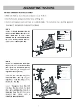
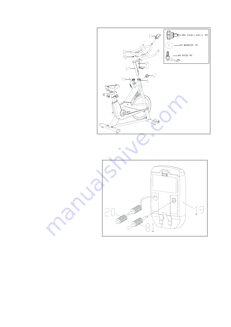
STEP 3:
Release the
Adjustment Knob (No. 10)
and insert
Handlebar Post (No. 17)
into
Main Frame (No. 1)
. Set at desired
height and then tighten
Adjustment
Knob (No. 10)
.
Attach
Handlebar
(No.
18)
to
Handlebar Post (No. 17)
using
L-Shaped Knob (No. 13)
and
Flat
Washer (No. 14)
.
NOTE:
Make sure
L-Shaped Knob (No.
13)
is securely tightened.
Attach
Computer
(No.
19)
to
Handlebar (No. 18)
. Connect the
Sensor
Wire (No. 20)
with the
computer’s extended wire
and plug the
Pulse Sensing Line (No. 81)
into the
holes on the back of
Computer (No.
19)
.
Summary of Contents for IC033
Page 2: ......
Page 4: ...3 EXPLODED DRAWING...
Page 18: ...17...
Page 19: ...18...
Page 20: ...19...


