background image

Mechanical Operations and Maintenance Manual for Industrial Robot ER10-1600

III

Content

Chapter One: Safety...................................................................................................................1

1.1 Instructions for Safe Use of Robots........................................................................1

1.1.1 Safety precautions during adjustment, operation, maintenance, etc............... 1

1.1.2 Safety Countermeasures of Robot Body......................................................... 3

1.2 Robot Body Label Description............................................................................... 7

1.3 Shift, Transfer, and Sale of Robots......................................................................... 8

1.4 Abandonment of Robots......................................................................................... 8

Chapter Two Basic Description............................................................................................... 10

2.1 Robot system composition....................................................................................10

2.2 Unpacking Check..................................................................................................10

2.3 Machine Body Nameplate.....................................................................................11

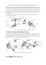
2.4 Body Part Composition and Direction Identification of Each Axis......................12

2.5 Robot Axis Range Limit and Home Position........................................................12

2.6 Robot Performance Parameters............................................................................ 12

2.7 Allowable Value of Wrist Payload........................................................................ 14

2.7.1 Allowable Weight....................................................................................... 15

2.7.2 Allowable Maximum of Static Payload Torque......................................... 15

Summary of Contents for ER10-1600

Page 1: ...ER10 1600 Mechanical Operation and Maintenance Manual for Industrial Robot EFORT INTELLIGENT EQUIPMENT CO LTD Hotline Tel 400 0528877...

Page 2: ...around you or property damage to the robot or other objects around you This announcement and manual are the latest version of this batch of products before delivery Please visit www efort com cn for...

Page 3: ...y Label Description 7 1 3 Shift Transfer and Sale of Robots 8 1 4 Abandonment of Robots 8 Chapter Two Basic Description 10 2 1 Robot system composition 10 2 2 Unpacking Check 10 2 3 Machine Body Namep...

Page 4: ...recautions 17 3 1 2 Auxiliary Handling Tooling 17 3 1 3 Handling Method 17 3 2 Robot Installation 19 3 2 1 Setting of Safety Fence 20 3 2 2 Robot Installation Method 20 3 2 3 Ground Mounting 20 3 2 4...

Page 5: ...rication 29 4 3 3 Lubricant Replacement Steps for J1 J4 Axis Reducer and Wrist Parts 29 4 3 4 Release the Residual Pressure in the Lubricating Oil Cavity 32 4 4 Timing Belt Maintenance 32 4 4 1 Timing...

Page 6: ...Mechanical Operations and Maintenance Manual for Industrial Robot ER10 1600 VI Appendix 42 A Screw Tightening Torque Table 42 B Backup List 42...

Page 7: ...rk clothes safety helmets safety shoes etc 2 When turning on the power make sure that there are no workers within the robot s operating range 3 The power must be cut off before entering the robot s ra...

Page 8: ...s Emergency situations generally have the following types 1 Low speed action suddenly becomes high speed action 2 Other operators performed the operation 3 A different program was started due to an ab...

Page 9: ...event the danger of the robot when the peripheral equipment is abnormal so as to ensure safe operation Attention The main body of the robot is a multi joint manipulator structure and the angle of each...

Page 10: ...tion object will not be released or fly out and the corner or protruding part should be treated to prevent damage to people and objects Attention It is strictly forbidden to supply power compressed ai...

Page 11: ...sconnect Raise your right hand and wave vigorously left and right 3 Is that OK to confirm Raise your right hand up high forward 4 OK Raise your right hand up high forward Use your thumb and index fing...

Page 12: ...eration only based on the memory and knowledge of the operator can cause accidents due to forgetting and mistakes Attention For the completed program use the storage protection function to prevent acc...

Page 13: ...the motor is hot and it is forbidden to touch it with bare hands Be careful of electric shock There is a risk of electric shock at the electrical connection of the robot It is generally pasted on the...

Page 14: ...s wrong operation or unsafe operation which may lead to accidents Attention When the robot is shifted transferred or sold abroad if there are no special provisions in the contract terms at the time of...

Page 15: ...ons and Maintenance Manual for Industrial Robot ER10 1600 9 Attention When carrying out abandoned work please pay full attention not to be pinched or injured Attention Waste products should be discard...

Page 16: ...pply cables etc Fig 2 1 Industrial Robot System Composition 2 2 Unpacking Check Attention 1 Before unpacking please confirm whether the outer packaging of the product is intact 2 After unpacking pleas...

Page 17: ...8 5m and it supports conventional customization of 12 5m 16 5 and 20 5m control cabinet power supply circular connector 10900001237 one PC Installed on the control cabinet 10900001229 one PC 109000012...

Page 18: ...bot Axis Range Limit and Home Position Each axis of the robot body has a home position and range limit When the robot system is running normally each axis of the robot is controlled to move within the...

Page 19: ...xis J3 axis 180 s axis J4 axis 330 s axis J5 axis 360 s axis J6 axis 600 s Maximum range of motion axis J1 axis 165 axis J2 axis 80 135 axis J3 axis 163 75 axis J4 axis 180 axis J5 axis 130 axis J6 ax...

Page 20: ...tallation method on the working space 2 7 Allowable Value of Wrist Payload Attention The installation payload at the front end of the robot wrist is affected by the allowable weight of the wrist the a...

Page 21: ...static payload torque J4 axis rotation J5 axis rotation J6 axis rotation ER10 1600 20 Nm 20 Nm 10 Nm 2 7 3 Allowable Maximum of Moment of Inertia Robot model Allowable moment of inertia J4 axis rotati...

Page 22: ...bed in the manual and confirm the weight and steps before proceeding If the operation cannot be performed in accordance with the specified method the robot and the control device may tip over or fall...

Page 23: ...orklift handling After handling remove the fork foot in time to avoid interference with the movement of the robot Fig 3 2 Fork Foot Installation Diagram 3 1 3 Handling Method 1 Handling method one Whe...

Page 24: ...e requirements of GB T 825 1988 The sling shall be able to bear the weight of the robot It is recommended that a single sling should bear more than 500kg 2 Forklift and hoisting lifting equipment shal...

Page 25: ...bot Installation Danger 1 Set up safety fence Otherwise accidents such as personal injury and equipment damage may occur The robot should be placed in a position where the tool and the tip of work pie...

Page 26: ...iciently then the safety protection shall be applied Access to hazardous areas shall be protected by safety guards such as guards and protection devices In order to avoid equipment damage and personal...

Page 27: ...e reference area 600mm 600mm chemical bolt group above M16 strength grade 4 8 eight fixing screws M16 45 strength grade 12 9 four taper pins with internal thread M12x45 two When installing on the grou...

Page 28: ...n the bracket and the ground Attention Measures such as the specification quantity and embedded depth of the chemical bolt group can be appropriately increased Improve the strength of the concrete fou...

Page 29: ...re tightening force requirements of the screws of this specification Fig 3 7 Suspended Installation 3 3 Installation Site and Environment The robot should be able to keep normal when used transported...

Page 30: ...l interface size As shown in the figure Remarks end load installation flange size Fig 3 8 end load installation size dimensions of the external component installed on the boom Fig 3 9 external compone...

Page 31: ...enance Manual for Industrial Robot ER10 1600 25 Fig 3 8 End Load Installation Flange Size Fig 3 9 Fig 3 10 Dimensions of the External Dimensions of the External Component Installed on the Boom Compone...

Page 32: ...3 11 Fig 3 12 Dimensions of External Component Installed on the Wrist Dimensions of External Component Installed on the Swivel Fig 3 13 Wiring Diagram of External Air Pipe and Signal Line Air pipe int...

Page 33: ...oise inspection check whether the transmission mechanism has abnormal noise 2 interference inspection check whether the transmission mechanism is running smoothly and whether there is abnormal vibrati...

Page 34: ...lubrication requirements Attention Note 1 Regarding cleaning parts mainly at the oil seal of the mechanical wrist cleaning chips and splashes 2 Regarding the fastening parts tighten the end effector...

Page 35: ...be controlled below 40cc 10 seconds J2 axis reducer 700cc J3 axis reducer 310cc J4 axis reducer 110cc Wrist parts 125cc 4 3 2 Space Orientation of Lubrication For lubricating oil replacement or replen...

Page 36: ...weight of the lubricant before and after refueling 3 The hose on the oil filling side is first filled with grease and be careful not to contain air in the grease 4 If the oil supply does not reach th...

Page 37: ...Specification Remarks 1 lubricant gun with the function of checking and counting oil supply 2 M10x1 oil supply joint 1 piece 3 8x1m oil supply hose one strip 4 weight meter Measure the weight of lubri...

Page 38: ...fore it is necessary to check the running status of the timing belt regularly recommended every six months If it is loose it should be tensioned in time If it is damaged it should be replaced in time...

Page 39: ...ming Belt Replacement The timing belt needs to be replaced every 3 years or every 11520 hours of operation of the robot At the same time customers should pay attention to the appearance of the timing...

Page 40: ...st have the following safety conditions 1 A safety fence and safety gate must be installed around the robot If the safety gate is not opened the operator cannot enter the safety fence An interlock swi...

Page 41: ...ols and methods of Home position calibration as well as some common problems and methods to solve these problems 1 Software Home position Calibration The laser tracker needs to be used to establish th...

Page 42: ...bot base and remove the battery pack as shown in Figure 4 6 Remove the old battery from the battery box and put the new battery into the battery box paying attention to the positive and negative polar...

Page 43: ...d torque The mounting base and the foundation are not firmly fixed 1 The ground installation conditions do not meet the requirements resulting in insufficient foundation rigidity 2 The specifications...

Page 44: ...g in phase in the early stage of its operation 1 Run at low speed first and gradually return to normal speed according to the improvement of noise 2 If the noise situation does not improve after runni...

Page 45: ...is a heat source in the operating environment of the robot increase the thermal insulation of protective clothing 2 Improve the ventilation conditions around the motor The motor is overheated due to i...

Page 46: ...can also cause oil leakage 1 Check whether the relevant parts are normal and replace them in time if they are abnormal 2 Check and ensure that the O ring is properly assembled 3 If the working environ...

Page 47: ...as broken wire unshielded twisted pair coupling with motor power line etc Check whether the motor encoder wiring is worn or disconnected If it is damaged check the cause of the cable damage and replac...

Page 48: ...700 one J1 J2Input gear 11200012701 one J2 Table 2 Sealing Ring and Screw Plug etc Name Material code Unit per robot Application area O ring rubber seal 103x3 55 two J1 J2 axis servo motor O ring rubb...

Page 49: ...t ER10 1600 43 Table 3 Sealant and others Name Model specification Unit per robot Application area grease MOLYWHITE RENO 00 2 5kg flat sealant THREEBOND 1110F one screw tightening agent THREEBOND 1374...

Page 50: ...his product are subject to change without prior notice The technical data and illustrations are for reference only and we reserve the right to change them EFORT INTELLIGENT EQUIPMENT CO LTD No 96 Wanc...

Reviews: