ER15-4-1600 Industrial robot quick user manual
第
30
页
Emergency stop should not be used for normal program stop, as this may
cause additional unnecessary wear and tear on the robot.
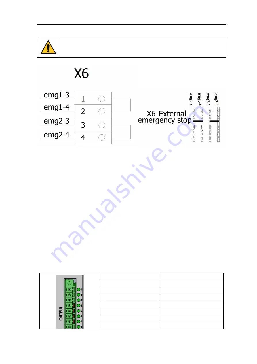
Figure 3-4 External emergency stop position indication and wiring schematic diagram
When it is necessary to connect an external emergency stop, you need to pull out the "short-circuit
bar" at the X6 terminal block in the emergency stop circuit, and connect the external emergency stop
button in series to the circuit. The user can wire as needed (recommended wire diameter above 0.5mm²),
as shown in the figure below Shown. The emg1-3 and emg1-4 circuits are 24V, the emg2-3 and emg2-4
circuits are 0V
3.4 I/O connection
3.4.1 Controller local IO definition
Table 3-3 OUTPUT port definition table
PIN
Description
1
System occupation
2
System occupation
3
Servo confirmation status
4
System occupation
5
System occupation
6
Custom
7
Custom

