ER15-4-1600 Industrial robot quick user manual
第
38
页
4.2 Power on
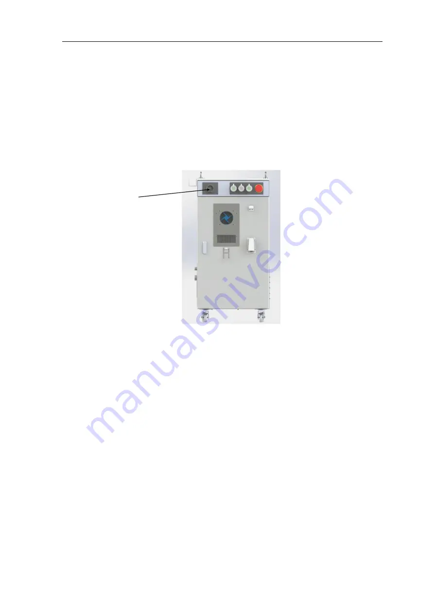
After mastering the button functions of the teach pendant in section 4.1, turn the power switch on
the upper left corner of the electric control cabinet to the right (OFF→ON) to start the system (as shown
in Figure 4-6). If everything is normal, turn on the teach pendant You can see that the system
automatically enters the login interface, and the user can operate the robot according to different
permissions; if there is an error message, please handle it according to the fault information or view the
fault handling manual according to the fault code.
Figure 4-6 Schematic diagram of electric control cabinet
4.3 Introduction to Coordinate System
The coordinate system is a position index system whose function is to determine the position
and posture of the industrial robot in space. The C30 operating system uses the following four
coordinate systems according to different reference objects:
1) Industrial robot-joint coordinate system;
2) Industrial robot-Cartesian coordinate system;
3) Industrial robot-tool coordinate system;
4) Industrial robot-user coordinate system
4.3.1 Industrial robot-joint coordinate system
The joint coordinate system is a coordinate system set in the joints of the industrial robot. In the
joint coordinate system, the position and posture of the industrial robot are based on the origin angle of
each joint base side, and the value in the joint coordinate system is the angle value of the joint rotation
in the positive and negative directions.
4.3.2 Industrial robot-Cartesian coordinate system
The position and posture of the industrial robot in the Cartesian coordinate system, through the
coordinate values x, y, z from the origin of the Cartesian coordinate system in space to the origin of
the Cartesian coordinate system on the tool side (tool center point) and the Cartesian coordinate system
Switch


