Mechanical Operation and Maintenance Manual for ER20-1100 Industrial Robot
23
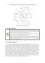
In order to avoid equipment damage and personal injury to the operator and surrounding
personnel during the operation of the robot, please set up the safety bar (with interlocking
door and other safety settings)!
Note: GB11291.2-2013 is equivalent to ISO 10218-2:2011.
3.2.2 Robot installation method
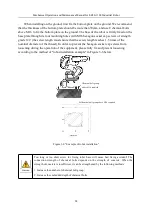
The robot installation, especially the fixed base and the foundation, can bear the dynamic
load of the robot when the robot is accelerated and decelerated and the static weight of the
robot and the clamp. In addition, when the mounting surface of the robot is not flat, it may
deform the robot and affect its performance.
Please ensure that the flatness of robot installation is below 0.5mm.
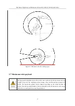
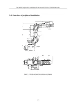
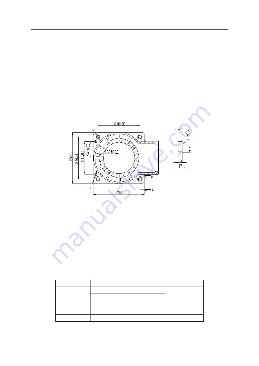
The dimensions of the base installation interface are shown in Figure 3-5 as follows:
Figure 3-5 Dimensions of ER20-1100 robot base
3.2.3 Ground installation
The ground installation requires that the concrete foundation is firm.The strength grade
and bearing capacity meet the relevant quality specifications. The concrete thickness shall not
be less than the landfill depth of chemical bolts, and the effective range shall completely
cover the fixed bottom plate, so as to ensure the safety and reliability of the bottom plate
installation. The concrete specifications refer to code for design of concrete structures GB
50010-2010 (2015 Edition) and GB 50010-2010 standard for performance test methods of
mechanical properties of ordinary concrete, and the strength grade refers to C20 / C25.
Table 3-1 Parts required for robot fixation
Name
Specification
Quantity
Bottom plate
thickness≥30mm
1
reference area
(
600mm×600mm
)
Chemical bolt
group
Above M16
,
strength grade≥4.8
8
Set screw
screw M16×45
,
strength grade 12.9
4
2 - ϕ12H7 Through-hole
4 - ϕ18 Through-hole


