EFORT Intelligent Equipment Co., Ltd
18
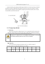
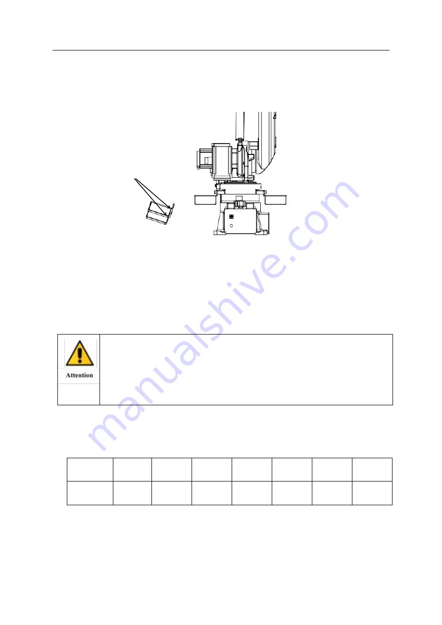
Attention should be paid to observing whether space for fork feet is reserved near the base of the robot
if a forklift is chosen for transporting. Because ER20-1700 does not reserve space for fork feet, external
fork feet should be installed to assist the forklift for transporting. The fork feet should be removed in time
to avoid interference with robot movement.
Fig. 3-2 Fork Foot Installation
3.1.3 Transporting Methods
1) Method One
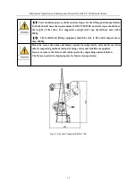
First set the robot posture according to Figure 3-3/3-4. Second install four M10 eyebolts on the
main frame, and then lift the robot with four steel ropes no longer than 3m. Rubber hose should be
used on the contact area of the steel rope and the robot body for protection.
In Figure 3-3/3-4, other devices are not installed on the end effector or robot arm.
Extra attention should be paid to once other devices are installed.
2
)
Method Two
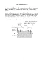
Set the robot posture according to the following chart. Use a forklift to transport it.
The angles of each axis in transportation posture are set as follows:
position
axis one
axis two
axis three
axis four
axis five
axis six
ER20-1700
joint
angle /°
0
+54
-54
0
-90
0
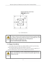
Two sides 4-M12X20


