EFORT Intelligent Equipment Co., Ltd.
14
(GB11291.2-2013) . It is stated in section 5.4 that the design and integration of a robot should reduce the
possibility of an operator being exposed to danger and a user should build up a safe space around a robot
taking the position and layout of the robot and the foreseeable danger into serious consideration. Section
5.10 requires that a user should set up the protection equipment on the entrance to the dangerous area if the
risk of danger cannot be eliminated or reduced.
Therefore, please set up a safety fence with safety interlock to prevent from physical injury or property
damage.
Note: The GB11291.2-2013 standard is equivalent to the ISO 10218-2:2011 standard.
2.4.2 Installation Procedures
The fixing of the robot base and the ground should be able to bear the dynamic load in robot
acceleration and deceleration and the fixture static weight. In addition, the robot might be deformed or its
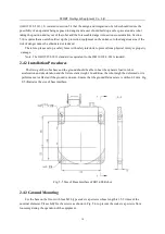
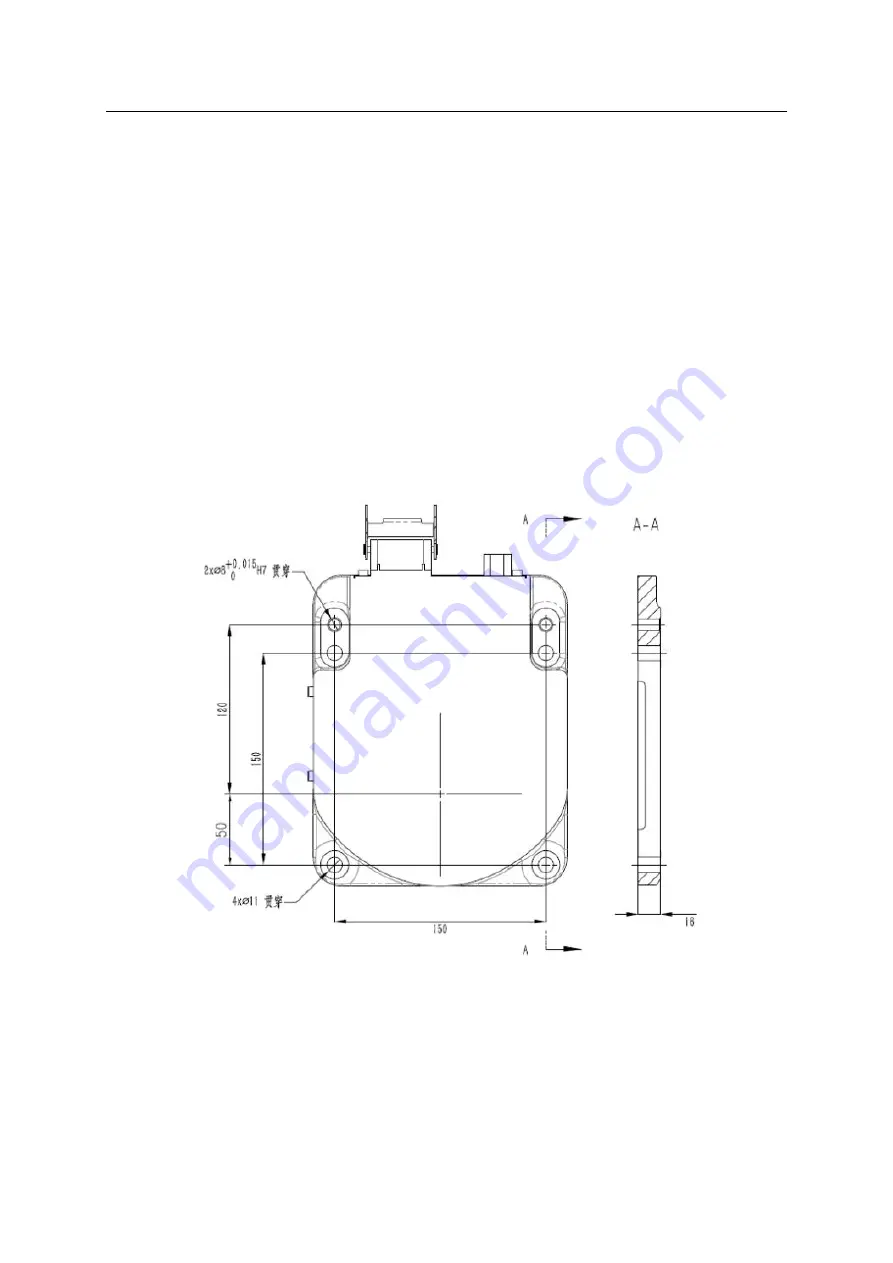
performance is affected if the ground is uneven. Ensure that the ground flatness rate is within 0.2 mm. Fig.
2-5 illustrates the size of base interface.
Fig. 2-5 Size of Base Interface of ER3-600 Robot
2.4.3 Ground Mounting
Fix the base on the floor with four M10 type socket cap screws whose length is 1.5-2 times of the
nominal diameter. Please fully fix the screws as shown in Fig. 2-6 to prevent the socket cap screws from
loosening during the operation of the equipment.
Summary of Contents for ER3-600
Page 2: ......
Page 4: ......
Page 54: ...EFORT Intelligent Equipment Co Ltd 48 Fig 4 10 Main Power Switch...


