ER6-1400V1.01
Industrial Robot Quick Operation Manual
20
2.4.7 Integrated application installation interface
The following table shows the robot body external interface size
Table 2-10 table of ER6-1400V1.01 robot external interface size
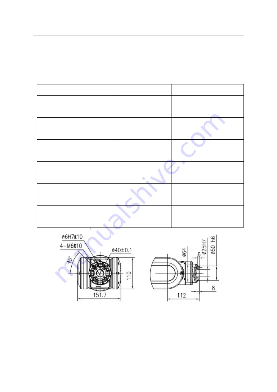
Figure 2-9 dimensions of end load mounting flange
Robot external interface size
shown in the figure
remark
Dimension of end load mounting
flange
Figure 2-9
dimension of end load mounting
Dimension drawing of external part
installed on big arm
Figure 2-10
installation dimension of external
parts
Dimension drawing of external parts
installed on motor base
Figure 2-11
installation dimension of external
parts
Dimension drawing of external parts
installed on wrist
Figure 2-12
installation dimension of external
parts
Dimension drawing of external parts
installed on swivel seat
Figure 2-13
installation dimension of external
parts
Wiring diagram of external air pipe
and signal line
Figure 2-14
external air pipe and signal line


