ER6-1400V1.01
Industrial Robot Quick Operation Manual
26
Table 3-2 cable category description
Cable category
description
robot power cable
transmit the driving power from the driving device in the control cabinet
to the robot motor
robot signal cable
transmits the encoder data to the serial measurement circuit board of the
driver
robot
grounding
cable
connect the robot body with the control cabinet.
There are four M32 * 1.5 cable locks on the left side of the control cabinet, which have been sealed
with sealing plugs when they leave the factory. Users must ensure the tightness when they use it, otherwise
the overall tightness of the control cabinet will be damaged.
3.3
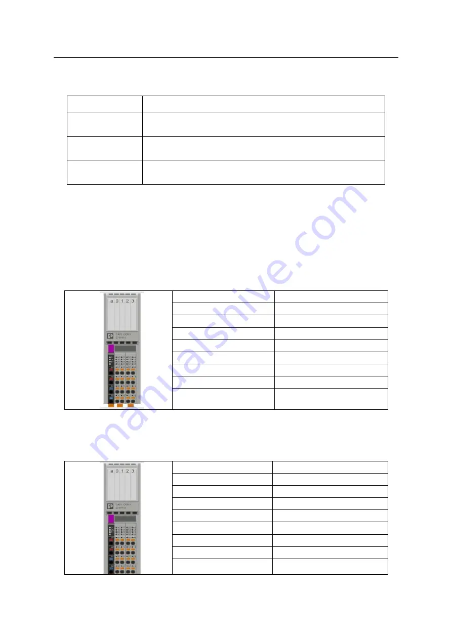
Controller local IO definition
Table 3-1 definition of OUTPUT port
PIN bit
Description
02
System occupancy
03
System occupancy
12
Servo confirmation status
13
System occupancy
22
System occupancy
23
System occupancy
32
User defined
33
User defined
With the IO output signal
,
except "user-defined" port, other ports are fixed functions used by the
system, which can not be changed. Users can expand body IO or remote IO module according to their
needs. Please consult EFORT for details.
Table 3-4 input definition table
PIN bit
Description
00
Emergency stop alarm 1
01
Servo enable
10
Servo confirmation
11
Hot swap of teach pendant
20
High temperature alarm
21
Emergency stop alarm 2
30
Safety door 1
31
Safety door 2


