ER6-1400V1.01
Industrial Robot Quick Operation Manual
41
3.6 Introduction of external emergency stop
The emergency stop button includes the emergency stop button of the teaching pendant, the
emergency stop button of the control cabinet and the external emergency stop button. The function of the
emergency stop button is to quickly cut off the output of the driver and make the robot stop immediately.
Turn the emergency stop button clockwise to release it.
An emergency stop is a state that takes precedence over all other robot controlled operations and will
cause all controlled hazards to stop, eliminate the motor power supply from the robot starter, remain valid
until reset, and can only be reset by manual operation. It means that all the power supply of the robot is cut
off from the emergency state except the circuit released by manual brake. You must perform the restore
steps, that is, reset the emergency stop button and clear the alarm to resume normal operation. The robot
system can be configured to stop the strike to produce any of the following effects:
• Class 0 stop
Stop the robot operation immediately by stopping the motor power supply
• Class 1 stop
Stop the robot operation while maintaining the motor power to maintain the robot
path. After completion, the motor power supply stops.
The default setting is 0 class stop. However, it is recommended to choose type 1 stop because it can
avoid unnecessary wear and tear of the robot and the additional operations needed to restore the system to
production.
The emergency stop function can only be used for its specific purpose and defined
conditions.
The emergency stop function is used to stop the equipment immediately in case of
emergency.
Emergency stop should not be used for normal program stop as this may cause additional
unnecessary wear to the robot.
3.6.1External emergency stop
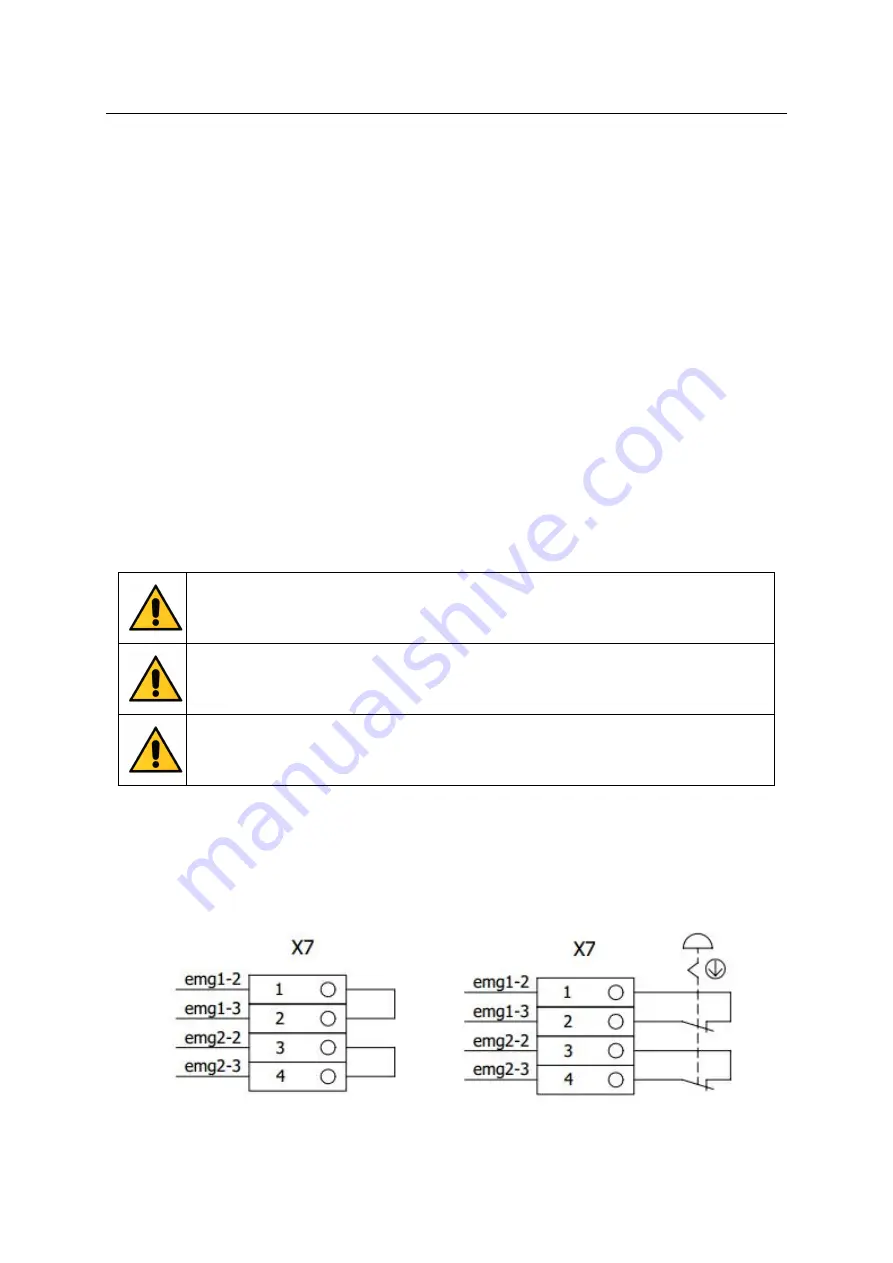
When external emergency stop is needed, pull out the "short-circuit strip" at X7 terminal block in the
emergency stop circuit, and connect the external emergency stop button in series into the circuit. The user
can connect the wire according to the need (the recommended wire diameter is more than 0.5mm), as
shown in the figure below.


