background image


MAINTENANCE  

A.  Maintenance after use 

Stains on the main body 

  Brush dust off and wipe off moisture with tissue paper. 

  Clean off any stains with a soft, dry cloth. 

  Excessive stains should be removed with a soft cloth soaked in a water diluted neutral 

detergent and squeezed dry. Do not use benzene, thinner, gasoline or chemicals. 

Stains on the glass surface 

Brush dust off 

Gently wipe off stains with a silicone cloth or a cleaning cloth for eye glass lenses. 

Excessive stains should be wiped off with soft cotton cloth impregnated with a cleaning liquid for 

eye glass lenses. 

Handling the battery 

If the instrument is not to be used for a long time, be sure to remove the batteries from the 

instrument and the detector and store them. 

Note: 

  Be sure not to use chemicals such as benzene, thinner or gasoline. 

  Be careful not to scratch the glass surface. 

  Leaving the batteries in the instrument for extended period may cause power consumption 

even if it is not in use. 

  If used battery is left in the battery holder, the instrument of the detector may be damaged 

by the battery fluid leakage. 

B.  Check and adjustment of the datum point 

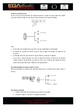
Horizontal check  

  Set up the instrument on the tripod 20m away from one wall so that the ‘X 1 side’ of the 

instrument faces the wall and turn it on or auto-leveling. 

  Turn on the detector. Keep adjusting its position for appropriate level mark on LCD display 

and mark the reference point (A) at the moment.  

  Loosen the center screw of the tripod to turn the instrument 180º to let X2 face one wall. 

  Readjust the detector position for appropriate level mark on LCD display and mark the 

reference point (B) at the moment. 

  There’s no need to adjust the unit if the distance between point A and B is no greater than 

3mm measured with target plate and ruler. 

Summary of Contents for 65512

Page 1: ......

Page 2: ...function for user s convenience High accuracy and low accuracy Options for different uses Fitted with remote control to operate most functions on the laser TECHNICAL DATA Battery voltage 4x1 5V D DC 5x 1 2V DC Ni H bat Operating time 40h 10h Laser wavelength 635nm Luminous power 1mW Precision Hor 0 1 mm m Ver 0 2 mm m Top laser point 0 15 mm m Operating ambient temperature 10ºC 50ºC Working distan...

Page 3: ...otor 4 Keypad 5 Lock for battery box 6 Battery cap 7 Emitting beam aperture 8 Bottom plate 9 LCD display 10 Accuracy switch 11 Power switch 12 Illumination switch 13 Buzzer switch 14 Plate vial 15 Fixing knob 16 Detector attaching screw 17 Beam reception window ...

Page 4: ...disposing of this instrument take a measure such as breaking the battery cap so that the laser will not be emitted PRECAUTIONS The instrument should not be stored or used in extreme temperature or job on a place subject to rapid change of temperature The instrument may not function properly if used out of the ambient temperature range Put into the carrying for storage and place in a dry area not s...

Page 5: ...RTION FOR THE DETECTOR Detector 1 Slide the battery cover while pushing its mark and remove it 2 Insert the accumulated dry battery into the battery holder according to its and marks 3 Slide the battery cover to reinsert it Caution Pay attention to the battery holder s and marks for proper battery insertion Batteries must be the same type Do not use a combination of batteries whose remaining capac...

Page 6: ... key When the speed is at 0rpm Press this key briefly to quick move the laser point Press and hold the key to move the rotor slowly In scan mode press and hold either of the key to change the scan line to point which moves slowly After releasing the key the unit will be back to scan mode and the scan line will be repositioned accordingly LEDs display 1 In the levelling process LED1 Blinks in red a...

Page 7: ...een Role of the remote control s keys PREPARATION FOR MEASUREMENT Setting up the tripod Arranging the tripod prepare the standard tripod for the instrument The dome head type and elevation type tripod for the instrument can be used Selection of the place to set up the tripod be sure to select a place where the job will not be interrupted and the instrument can be set to have almost same distance t...

Page 8: ...secure it using the tripod center screw Placing on the wall mount Note Also when removing the instrument from the tripod loosen the center screw while supporting the instrument with one hand Do not leave the instrument placed on tripod without the center screw being tightened It may cause the instrument to fall and be damaged Arranging the detector Installing the rod adapter 1 Place the instrument...

Page 9: ...ically When levelling is completed the rotor begins to rotate and emits visible laser beam 3 To select the manual mode press and hold this key for more than 3 seconds 4 To press the speed key to select of rotor 4 grades 600rpm 300rpm 5rpm 0rpm circulating in above sequence by each pressing In cal mode speed will shift between 0rpm and 600rpm 5 When the speed is 0rpm press the scan key to enter sca...

Page 10: ...After self leveling the operation is same as the operation 6 After turn on the unit press and hold the I O key for more than 3 seconds it will enter manual mode The operation is same as the operation Note Before operating the instrument perform the check and adjustment of the datum point In the manual mode please be noted that the horizontal accuracy of emitted laser beam is not guaranteed When sp...

Page 11: ... jack located on the battery pack 3 Plug the charger into an electrical outlet 110volts or 220volts depending on charger and country 4 After charge for 4 hours the LED on the charger will be charged the colour 5 When the battery s power is low remove the battery pack from the unit and charge it 6 For optimum life of the battery it is recommended to charge the battery after fully discharged To assu...

Page 12: ... reference level detecting accuracy Push the detection accuracy selection switch to select the needed detection accuracy High accuracy detection To be selected for detecting the reference level with accuracy Low accuracy detection To be selected if high accuracy is not needed or when stable reference level cannot be obtained due to slight vibration at job site Note For the detection accuracy to be...

Page 13: ...received and any switch is not operated for about one minute To illuminate the display again push the illumination switch once more Detecting the reference level At the measuring point set the position of the detector nearly to the height to the beam emitting aperture of the instrument Position the detector where the buzzer sound or the beam reception display appears by directing the detecting dis...

Page 14: ... the plain rod s top or bottom end Note If a line was marked along the detector s top or bottom end be sure to make measurement compensation as described on the back of the detector The detector should previously be positioned correctly on the plain rod according to the reference mark Reading the regleta After the reference level has been detected read the regleta using the index on the rod adapte...

Page 15: ...inner or gasoline Be careful not to scratch the glass surface Leaving the batteries in the instrument for extended period may cause power consumption even if it is not in use If used battery is left in the battery holder the instrument of the detector may be damaged by the battery fluid leakage B Check and adjustment of the datum point Horizontal check Set up the instrument on the tripod 20m away ...

Page 16: ...d spot key to help you to fine tune the laser beam to desired position If there is still a bit from accessibility you may reach for it by slightly turning the unit Bring the laser point to the center of the reference point A and B by pressing slope key briefly If X2 faces one wall and the laser beam is projected in the reference direction move down the laser beam by pressing of slope key After app...

Page 17: ...the vertical axis needs calibrating Vertical Calibration Before switching to calibration mode press I O key Then press cal key for more than 5 seconds and release it to bring the rotation head to a stop LED3 will blink in green which indicates the axis Z calibration is in progress Aim the laser point at the upper section of plumb string just by positioning the instrument accordingly then use spot ...

Page 18: ...chequeo y autonivelación disponibles para el usuario También las opciones de alta y baja precisión para diferentes usos Equipado con control remoto para manejar la mayoría de funciones del láser FICHA TÉCNICA Fuente de alimentación 4x1 5V D DC 5x 1 2V DC Ni H bat Autonomía 40h 10h Longitud de onda 635nm Potencia del láser 1mW Precisión Hor 0 1 mm m Ver 0 2 mm m Top laser point 0 15 mm m Tª de trab...

Page 19: ...tapa de la batería 6 Tapa batería 7 Apertura de emisión de rayos 8 Placa inferior 9 Pantalla LCD 10 Interruptor de precisión 11 Interruptor de encendido 12 Interruptor de iluminación 13 Interruptor del timbre 14 Ampolla 15 Tornillo de sujección 16 Parte de sujeción del tornillo 17 Ventana recepción rayos ...

Page 20: ... batería para evitar la emisión de rayos láser PRECAUCIONES El aparato no debe ser usado en ambientes de temperaturas extremas o de cambios bruscos de temperatura ya que su funcionamiento podría verse alterado Colocar el aparato en su bolsa para su almacenamiento y guardarlo en un ambiente seco libre de polvo vibraciones y elevados niveles de humedad Al almacenar el aparato éste debe permanecer en...

Page 21: ...ntroducir la batería en su soporte teniendo en cuenta la correspondencia con los símbolos y 3 Desplazar la tapa de la batería para volver a introducirla Advertencia Especial atención a las indicaciones y al introducir la batería Las baterías deben ser del mismo tipo No utilizar baterías cuya duración sea distinta PANTALLA Y PANEL Función del panel BOTÓN FUNCIÓN Botón de operaciones Botón I O MAN B...

Page 22: ... es 0rpm Pulsar el botón brevemente para desplazar el láser Pulsar y mantener el botón para mover el rotor despacio En modo escaneo pulsar cualquiera de los botones para cambiar la línea de escaneo al punto que se mueve lentamente Al dejar de pulsar el botón la unidad volverá al modo escaneo y la línea de escaneo se posicionará adecuadamente Pantalla LED 1 En el proceso de nivelación LED1 parpadea...

Page 23: ...ridos 10 segundos 6 Modo calibración con la unidad en la dirección del eje Z LED3 parpadeará en verde Función de las botones de control remoto Boton de escanear LED Boton de pendiente Boton de velocidad Boton Punto PREPARACIÓN PARA LA MEDICIÓN Montaje del trípode Colocación del trípode preparar el trípode para colocar el instrumento La dirección del nivel y el grado de elevación pueden ser graduad...

Page 24: ...tiempos Para situarlo en suelo resbaladizo deben asegurarse las patas Utilizar cadenas para evitar la extensión de las patas Instalación instrumental Colocación en trípode Colocar el instrumento en la cabeza del trípode y mientras se sujeta el instrumento con una mano asegurarla mediante el tornillo central Montaje en la pared Nota Al desmontar el instrumento del trípode aflojar el tornillo centra...

Page 25: ...os se iniciará el modo manual 2 El rayo rotará aun si el nivel no está nivelado Por seguridad la luz verde situada en la parte superior se el botón I O se cambiará a roja para avisar al usuario de que el láser se encuentra en modo manual 3 En este modo la función pendiente puede utilizarse 4 Este modo se utilizará cuando sea necesario trabajar en planos inclinados FUNCIONAMIENTO HORIZONTAL 1 Pulsa...

Page 26: ...ara calibrar la precisión en los ejes X Y Para girar el nivel pulsar el botón I O FUNCIONAMIENTO VERTICAL En esta posición no se requieren accesorios El nivel puede colocarse directamente sobre el suelo No obstante para una mejor instalación puede colocarse en la pared 1 Colocar la unidad en posición vertical sobre el punto de apoyo Utilizar las patas ajustables para ajustar la ampolla del nivel 2...

Page 27: ...n pendiente no estará disponible Mientras la unidad no está en funcionamiento debe permanecer apagada Apagar el aparato al pasar de la posición horizontal a la posición vertical de trabajo Advertencia Mientras el aparato está en funcionamiento evitar exponer los ojos al rayo láser foco de luz roja La exposición prolongada puede ser prejudicial para los ojos ENCENDIDO 1 Antes del primer uso la bate...

Page 28: ...dido se apagará Nota El interruptor de encendido se encuentra pulsado en la pantalla de cristal líquido como muestra la figura superior lo permite la detección de cualquier defecto en la pantalla La capacidad restante de la batería se encuentra indicada mientras esté encendido Controlar cuándo es necesario el cambio de batería mediante el indicador superior Si durante 10 minutos no se pulsa botón ...

Page 29: ...ección de precisión se inicia cuando se enciende el aparato Si el punto a medir está lejos del nivel de referencia puede no exponerse de manera estable debido al acuñamiento de ondas de calor o leve vibración del instrumento Bajo estas condiciones seleccionar Detección de baja precisión Encendido Apagado del timbre receptor de rayos Pulsar el interruptor de recepción de rayos para determinar si el...

Page 30: ... de rayos láser Posicionar el detector donde suena el timbre o se visualiza la recepción de rayos láser dirigiendo el detector hacia el instrumento y moviendo el detector arriba y abajo Mover el detector arriba y abajo de acuerdo con el detector de rayos o timbre y obtener el nivel de referencia Mover el detector hacia abajo cuando esta posicionado arriba El timbre suena en intervalos cortos Esta ...

Page 31: ...ribe en la parte de atrás del detector El detector debe posicionarse correctamente en la varilla plana de acuerdo con la marca de referencia Lectura de la regleta Una vez detectado el nivel de referencia leer la regleta utilizando el índice del adaptador de la barra adaptadora Nota Una vez detectado el nivel de referencia aflojar levemente el tornillo del adaptador de la varilla y mover el detecto...

Page 32: ...zar productos químicos como benceno disolvente o gasolina No arañar la superficie del cristal La no extracción de baterías en instrumentos que no se van a utilizar puede provocar el consumo de energía Si una batería usada se deja en el portabaterías el instrumento del detector puede resultar dañado por un escape de fluido de la batería 7 Revisión y ajuste de los datos del punto Revision horizontal...

Page 33: ... preferible pulsar prolongadamente el botón punto para mejorar la puesta a punto del rayo láser en la posición deseada Si hay accesibilidad se debe llegar a ella mediante un leve giro de la unidad Llevar el punto del láser al centro de referencia A y B pulsando brevemente el botón pendiente Si X2 esta frente a una pared y el rayo lá0ser esta proyectado en la dirección de referencia bajar el rayo l...

Page 34: ... cuerda hasta la parte inferior Si la desviación supera los 3 mm el eje vertical debe ser calibrado Calibración vertical Antes de iniciar el modo de calibración pulsar el botón I O Pulsar el botón Cal durante más de 5 segundos y soltarlo para detener el cabezal de rotación LED3 parpadeara en verde lo que indica que se el eje Z esta siendo calibrado Dirigir el extremo del láser a la parte superior ...

Page 35: ...PARTIR DE LA FECHA DE COMPRA EJEMPLAR PARA EGA MASTER CERTIFICADO DE GARANTIA SELLO DEL DISTRIBUIDOR ARTICULO Nº DE SERIE DISTRIBUIDOR PAIS TELEFONO FECHA DE VENTA NOMBRE DEL COMPRADOR TELEFONO DEL COMPRADOR EGA MASTER GARANTIZA AL COMPRADOR DE ESTA MAQUINA LA GARANTIA TOTAL DURANTE 12 MESES DE LAS PIEZAS CON DEFECTOS DE FABRICACION ESTA GARANTIA NO CUBRE AQUELLAS PIEZAS QUE POR SU USO NORMAL TIEN...

Page 36: ...ASTER WITHIN 7 DAYS FROM SALE DATE COPY FOR EGA MASTER GUARANTEE CERTIFICATE DISTRIBUTOR STAMP SPAIN ITEM SERIE Nº DISTRIBUTOR COUNTRY PHONE SALE DATE BUYER NAME BUYER PHONE EGA MASTER GUARANTEES TO THE BUYER OF THIS MACHINE THE TOTAL WARRANTY DURING 12 MONTHS OF THE PIECES WITH MANUFACTURING FAULTS THIS GUARANTEE DOES NOT COVER THOSE PIECES WORN OUT DUE TO A NORMAL USE IN ORDER TO OBTAIN THE VALI...

Reviews: