39
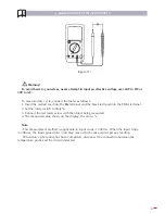
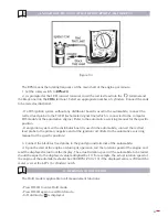
2. Set the rotary switch to
12V
.
3. Connect the test leads across with the object beingmeasured. Red test lead to the positive
polarity andblack test lead to the negative polarity.
4. The measured value shows on the display, the unit is
V
.
Note
- The Meter is only applicable to measure less than 20V non-working battery. To measure the
working battery, it is necessary to add up the working loading and the Meter built-in loading.
- The Meter has a built-in 120Ω/2W loaded resistance, the measured value shown on the display
is the value of the loaded battery.
- When battery testing has been completed, disconnect the connection between the testing lead
and the circuit under test.
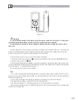
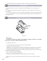
H. TEMPERATURE MEASUREMENT (SEE FIGURE 9)
(figure 9)
Warning!
To avoid harm to yourselves, never attempt to input
an effective voltage over 60V in DC or 30V in AC.
The temperature measurement range is -40ºC ~ 1000ºC.
To measure temperature, connect the Meter as below:
1. Insert the red test lead into the
terminal and the black test lead into the
COM
terminal.
2. Set the rotary switch to ºC.
3. Place the temperature probe on the outside or internal of the object being measured.
4. The measured value shows on the display, the unit is ºC.
Note
- Please choose a correct temperature probe. The included temperature probe can only measure
up to 250ºC. You need to select another temperature probe for any measurement higher than
250ºC.
- The Meter display “
1
” when there is no signal input.
- The Meter display its internal nearest temperature value when the two input terminals are
shorted.
- When temperature testing has been completed, disconnect the connection between the
temperature probe and the circuit under test.
Summary of Contents for egatronic 51259
Page 50: ...50...

