background image

Summary of Contents for EGAtronik 51255

Page 1: ...MULT METRO DIGITAL DIGITAL MULTIMETER MULTIM TRE DIGITAL ESPA OL 2 ENGLISH 18 FRAN AIS 34 GARANTIA GUARANTEE GARANTIE 49 COD 51255 MANUAL DE INSTRUCCIONES OPERATING INSTRUCTIONS MANUEL D INSTRUCTIONS...

Page 2: ...da os personales y para evitar posibles da os al Medidor o al equipo bajo prueba siga las siguientes instrucciones Antes del uso del medidor inspeccione la carcasa No use el medidor si sta est da ada...

Page 3: ...elo antes de abrir la tapa Al reparar el Medidor use solamente el mismo n mero de modelo o repuestos de id nticas especificaciones el ctricas El circuito interno del Medidor no debe ser alterado para...

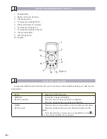
Page 4: ...iguiente tabla muestra informaci n acerca de las funciones desempe adas por cada uno de los botones Bot n Operaci n desempe ada POWER Bot n amarillo Enciende y apaga el Medidor Presione una vez para e...

Page 5: ...de bater a no sea mostrado en la pantalla de otro modo pueden producirse falsas lecturas Preste atenci n al s mbolo localizado en la proximidad de los terminales de entrada antes de llevar a cabo sus...

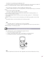
Page 6: ...ra 1 Inserte el cable de prueba rojo en el terminal de entrada y el cable de prueba negro en el terminal de entrada COM 2 Gire el selector giratorio hasta una posici n de medida apropiada 3 Conecte lo...

Page 7: ...de 200mA inserte el cable de prueba rojo en el terminal mA mientras que si es igual o superior a 200mA inserte el cable de prueba rojo en el terminal 10A o 20A 3 Gire el selector giratorio hasta un r...

Page 8: ...lado m s positivo del corte y el negro al lado m s negativo 5 Encienda la energ a del circuito El valor de la medici n ser mostrado en la pantalla Nota Si el valor de la corriente a medir es desconoc...

Page 9: ...i n entre los cables de prueba y el circuito bajo prueba F MEDICION DE CAPACIDAD VEA FIGURA 6 Advertencia Para evitar da os al medidor o a los objetos bajo prueba desconecte la energ a del circuito cu...

Page 10: ...e silicio cae entre 0 5 V y 0 8V Para probar el diodo fuera de un circuito conecte el medidor de la siguiente manera 1 Inserte el cable de prueba rojo en el terminal de entrada V y el cable de prueba...

Page 11: ...si la resistencia del circuito bajo prueba es T 70 indicando circuito da ado Puede o no que se emita un sonido si la Resistencia del circuito bajo prueba est entre 10 y 70 La pantalla mostrar el valo...

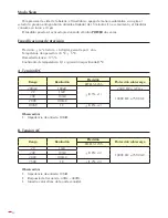
Page 12: ...mperatura de operaci n 23 C 5 C Humedad relativa 75 Coeficiente de temperatura 0 1 x precisi n especificada 1 C A Tensi n DC Rango Resoluci n Precisi n Protecci n sobrecarga COD 51255 200mV 100 V 0 5...

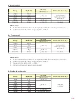
Page 13: ...Precisi n Protecci n sobrecarga COD 51255 200 A 0 1 A 1 3 0 315A 250V fusible tipo r pido 5x20mm 2mA 1 A 20mA 10 A 200mA 100 A 1 8 3 10A 20A 10mA 3 5 Un fused Observaci n En 10A Para medici n continu...

Page 14: ...rto Aprox 2 8V Sonido de continuidad 1 Aprox 70 suena continuamente H Transistor Test Rango Observaci n Condiciones de prueba hFE Puede medir NPN Vce 2 8V 1bo 10 A I MANTENIMIENTO Esta secci n se incl...

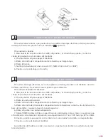
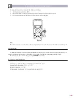
Page 15: ...ente procedimiento Para sustituir el fusible del Medidor 1 Desconecte la conexi n entre los cables de prueba y el circuito bajo prueba y retire los cables de prueba de los terminales del medidor 2 Pre...

Page 16: ...deben ser recogidos y dispuestos por separado Si usted tiene que tirar por favor no use la basura habitual Por favor p ngase en contacto con su distribuidor para el reciclaje de forma gratuita GARANT...

Page 17: ......

Page 18: ...njury and to avoid possible damage to the Meter or to the equipment under test adhere to the following rules Before using the Meter inspect the case Do not use the Meter if it is damaged or the case o...

Page 19: ...e When servicing the Meter use only the same model number or identical electrical specifications replacement parts The internal circuit of the Meter shall not be altered at will to avoid damage of the...

Page 20: ...tch 10 Power FUNCTIONAL BUTTONS Below table indicated for information about the functional button operations Button Operating performed POWER Yellow Button Turn the Meter on and off Press down the POW...

Page 21: ...n the LCD after turning on the Meter Make sure the Low Battery Display is not on otherwise false readings may be provided Pay attention to the symbol which is located besides the input terminals of th...

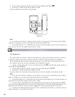
Page 22: ...as follows 1 Insert the red test lead into the input terminal and the black test lead into the COM input terminal 2 Set the rotary switch to an appropriate measurement position in range 3 Connect the...

Page 23: ...he rotary switch to an appropriate measurement position in A range 4 Break the current path to be tested Connect the red test lead to the more positive side of the break and the black test lead to the...

Page 24: ...isplay Note If the value of current to be measured is unknown use the maximum measurement position 20A and 20A terminal or 10A and 10A terminal and reduce the range step by step until a satisfactory r...

Page 25: ...tested circuit power when measuring on line capacitors and discharge all high voltage capacitors before measuring capacitance Use the DC voltage function to confirm that the capacitor is discharged Ne...

Page 26: ...ds to the proper terminals as said above to avoid error display The LCD will display 1 indicating open circuit for wrong connection The unit of diode is Volt V displaying the positive connection volta...

Page 27: ...has been completed remove the transistor from the transistor jack Sleep Mode To preserve battery life the Meter automatically turns off if you do not turn the rotary switch or press any button for aro...

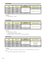
Page 28: ...DC or 750V AC 20V 10mV 200V 100mV 750V 1V 1 2 3 Remark Input impedance 10M Frequency response 40Hz 400Hz Display effective value of sine wave mean value response C DC Current Range Resolution Accuracy...

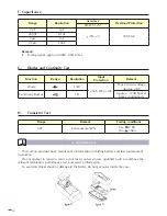
Page 29: ...drop Full range at 200mV Frequency response 40Hz 400Hz Display effective value of sine wave mean value response E Resistance Test Range Resolution Accuracy Overload Protection COD 51255 200 0 1 0 8 3...

Page 30: ...Continuity Buzzer 1 Approx 70 buzzer beeps continuously H Transistor Test Range Remark Testing conditions hFE Can measure NPN Vce 2 8V 1bo 10 A I MAINTENANCE This section provides basic maintenance in...

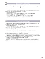
Page 31: ...fuses ONLY in accordance with the following procedure To replace the Meter s fuse 1 Disconnect the connection between the testing leads and the circuit under test and remove the testing leads away fro...

Page 32: ...se ones must be collected and arranged separately If you have to throw them out please do not use the usual rubbish Please contact your distributor for free recycling GUARANTEE The maker guarantees to...

Page 33: ...33...

Page 34: ...rtissement Pour viter d ventuelles d charges lectriques ou des dommages personnels au mesureur ou l quipement mis l preuve suivez les consignes suivantes Avant d utiliser le mesureur examinez le bo ti...

Page 35: ...ou des dommages personnels Retirez les c bles mis l preuve du mesureur et teignez le avant d ouvrir le couvercle Lors de la r paration du mesureur utilisez seulement le m me num ro de mod le ou des pi...

Page 36: ...ES BOUTONS Le suivant tableau pr sente les fonctions de chacun des boutons Bouton Fonction POWER Bouton jaune Allumer et teindre le mesureur Appuyez une fois pour allumer le mesureur Appuyez nouveau p...

Page 37: ...l indicateur de batterie n est pas affich sur l cran autrement de fausses lectures peuvent se produire Faites attention au symbole situ proximit des bornes d entr e avant d effectuer les mesures A ME...

Page 38: ...ter des d charges lectriques Pour mesurer des tensions CA connectez le mesureur de la mani re suivante 1 Ins rez le c ble mis l preuve rouge dans la borne d entr e et le c ble mis l preuve noir dans l...

Page 39: ...le borne mA or 20A ou 10A et le c ble mis l preuve noir dans le borne COM Quand vous mesurerez des courants au dessous de 200 mA ins rez le c ble mis l preuve rouge dans le borne 10A ou 20A 3 Tournez...

Page 40: ...ir au c t le plus n gatif 5 Allumez l nergie du circuit La valeur de la mesure sera affich e sur l cran Note Si la valeur du courant mesurer est inconnue utilisez la position maximale de mesure 20A et...

Page 41: ...e d branchez la connexion entre les c bles mis l preuve et le circuit sous preuve F MESURE DE CAPACIT VOIR FIGURE 6 Avertissement Pour viter des dommages au mesureur ou aux objets mis l preuve d bran...

Page 42: ...0 5 V et 0 8 V Pour prouver le diode en dehors d un circuit connectez le mesureur de la mani re suivante 1 Ins rez le c ble mis l preuve rouge dans la borne d entr e V et le c ble mis l preuve noir d...

Page 43: ...circuit sous preuve est T 70 ce qui indique un circuit endommag Il est possible qu un son soit mis si la r sistance du circuit sous preuve se trouve entre 10 et 70 L cran affichera la valeur de r sis...

Page 44: ...Temp rature d op ration 23 oC 5 oC Humidit relative 75 Coefficient de temp rature 0 1 x pr cision sp cifi e 1 oC A Tension CC Rang R solution Pr cision Protection surcharge COD 51255 200mV 100 V 0 5...

Page 45: ...sion Protection surcharge COD 51255 200 A 0 1 A 1 3 0 315A 250V fusible type rapide 5x20 mm 2mA 1 A 20mA 10 A 200mA 100 A 1 8 3 10A 20A 10mA 3 5 Un fused Observation En 10A pour une mesure continue de...

Page 46: ...e continuit 1 Approx 70 sonne sans cesse H Transistor Test Rang Observation Conditions d preuve hFE Peut mesurer NPN Vce 2 8V 1bo 10 A I ENTRETIEN Cette section inclut des informations essentielles po...

Page 47: ...t suivez ces instructions 1 D branchez la connexion entre les c bles mis l preuve et le circuit sous preuve et retirez les c bles mis l preuve des bornes du mesureur 2 Appuyez sur le bouton off pour t...

Page 48: ...48...

Page 49: ...A PARTIR DE LA DATE D ACHAT EJEMPLAR PARA EGA MASTER COPY FOR EGA MASTER EXEMPLAIRE POUR EGA MASTER ARTICULO ITEM ARTICLE N DE SERIE SERIE N N SERIE DISTRIBUIDOR DISTRIBUTOR DISTRIBUTEUR PAIS COUNTRY...

Page 50: ......

Page 51: ......

Page 52: ...C ZORROLLETA 11 POL IND JUNDIZ 01015VITORIA SPAINP O B APTDO 5005 TEL 34 945 290 001 FAX 34 945 290 141 info egamaster com www egamaster com...

Reviews: