2
INSTALLATION
EG4xxx Owner’s Manual
2.7.2
AC Mains Connector
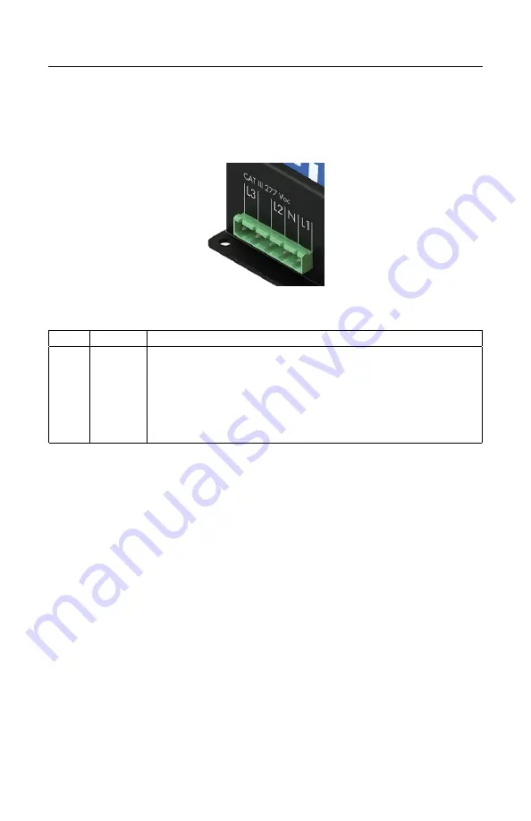
This connector is shown in Figure 3 and the pin-out is as follows:
Figure 3: AC Mains Connector
Pin:
Name:
Description:
1
L1
Wire to phase 1 of building supply.
2
N
Wire to building’s Neutral.
3
L2
Wire to phase 2 of building supply for split- and three-phase
installs.
4
Unused. Leave unconnected.
5
L3
Wire to phase 3 of building supply for three-phase installs.
The AC Mains Connector is CAT III rated (for measurements performed in the
building installation, such as circuit breakers). Pin L1 serves three purposes: it
powers the device (2W typical, 12W maximum), the voltage on the line is mea-
sured to calculate power used/generated on phase L1, and it carries the power-
line signal for communicating with the HomePlug AV wall-plug adapter. The pin
must be wired to the building’s power supply with a voltage in the range from 85–
277Vrms (to neutral). In contrast, pins L2 and L3 are used purely as voltage-taps
so power used/generated on phases L2 and L3 can be calculated. Wiring these pins
is necessary only if there are CTs measuring current(s) on L2/L3. The voltage on
these lines can be 0–277Vrms (Vac or Vdc).
To measure any signal on the AC Mains Connector L1 and N must be powered
with at least 85Vrms. If no voltage is supplied to this port, then the unit will
not measure any signal from L1, L2, or L3. The unit can continue to operate if
powered by the DC port.
Warning
: The eGauge requires an appropriate N terminal connection (see con-
figuration guide wiring diagrams for examples). If AC voltage is applied without
an appropriate N connection, damage to the unit may occur.
7
April 6, 2022


