EG4xxx Owner’s Manual
2
INSTALLATION
2.7.3
DC Connector
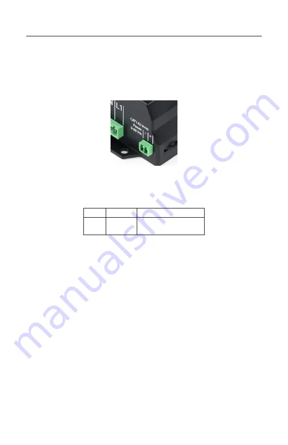
This connector is shown in Figure 4 and the pin-out is as follows:
Figure 4: DC Connector
Pin:
Name:
Description:
1
+
Wire to DC signal.
2
-
Wire to ground.
The DC Connector CAT III rated for use from -60 – 60Vdc. It can measure the
voltage across that full range but if powered by the DC port, there must be at
least 9Vdc. If an installation utilizes both the AC Mains Connector as well as
DC Connector, and DC power is used to power the unit, there must be more than
12Vdc to ensure unit pulls power from the DC port.
2.7.4
CT Connector
This connector is shown in Figure 5. It provides 15 or 30 positions for the CT
plugs illustrated in Figure 9. The silk-screened numbers indicate which CT should
be connected to which pair of pins. Pins that are to receive the black wire of the
CTs are marked with a circle with black interior, pins for the white wires are
marked with a circle with white interior.
April 6, 2022
8


