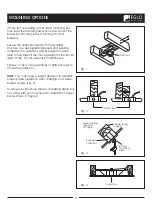
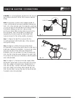
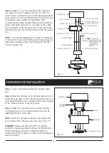
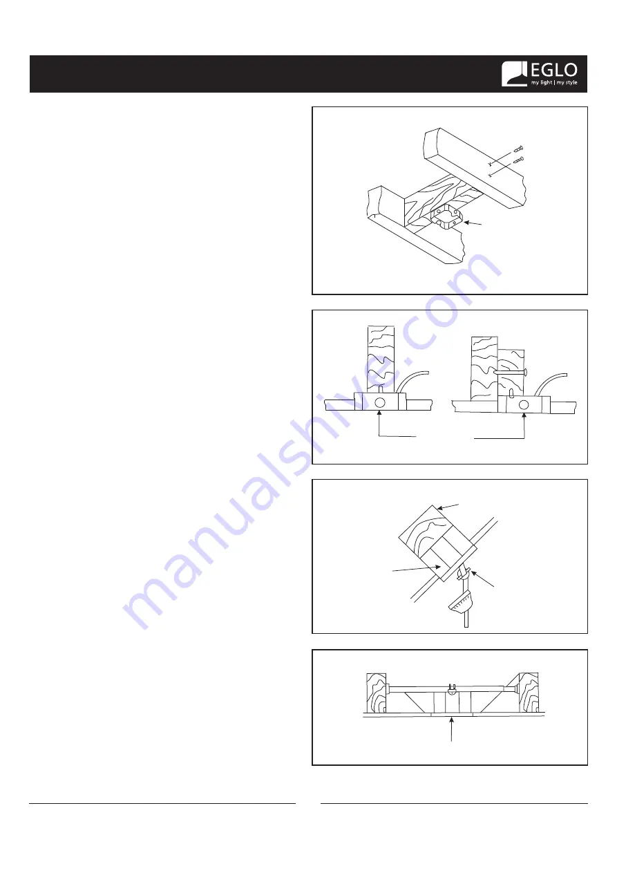
background image

MOUNTING OPTIONS

3

If there isn't an existing UL/CUL listed mounting box, 

then read the following instructions. Disconnect the 

power by removing fuses or turning off circuit 

breakers.

Secure the outlet box directly to the building 

structure. Use appropriate fasteners and building 

materials. The outlet box and its support must be 

able to fully support the moving weight of the fan (at 

least 35 lbs). Do not use plastic outlet boxes.

Figures 1,2 and 3 are examples of different ways to 

mount the outlet box.

NOTE:


You may need a longer downrod to maintain 

proper blade clearance when installing on a steep, 

sloped ceiling. (Fig. 3)

To hang your fan where there is an existing fixture but 

no ceiling joist, you may need an installation hanger 

bar as shown in Figure 4.

Outlet box

Provide strong

support

Recessed

outlet box

Outlet  box

Outlet box

Fig. 1

Fig. 2

Fig. 3

Fig. 4

Ceiling

mounting

plate

Angled ceiling

maximum

20° angle 

Summary of Contents for Whitehaven 203229A

Page 1: ... CEILING FAN OWNER S MANUAL Read and Save These Instructions Whitehaven 203229A 203231A 203232A ...

Page 2: ...ate g LED Light kit h Glass shade i Receiver 3 wire nuts j Transmitter holder 2 mounting screws k 9 Volt battery l Package hardware 1 Mounting hardware screws 2 lock washers 2 star washers 2 wire nuts 3 wood screws 2 2 Blade attachment hardware screws 16 fiber washers 16 3 Balance Kit 1 PACKAGE CONTENTS Philips screw driver Blade screw driver 11 mm wrench Step ladder Wire cutters a b c d e f g h i...

Page 3: ...an blades are in motion Fan must be turned off and blades stopped before reversing blade direction 8 Avoid placing objects in the path of the blades 9 To avoid personal injury or damage to the fan and other items be cautious when working around or cleaning the fan 10 Do not use water or detergents when cleaning the fan or fan blades A dry dust cloth or lightly dampened cloth will be suitable for m...

Page 4: ... moving weight of the fan at least 35 lbs Do not use plastic outlet boxes Figures 1 2 and 3 are examples of different ways to mount the outlet box NOTE You may need a longer downrod to maintain proper blade clearance when installing on a steep sloped ceiling Fig 3 To hang your fan where there is an existing fixture but no ceiling joist you may need an installation hanger bar as shown in Figure 4 O...

Page 5: ... canopy cover canopy and then through the ball downrod Fig 7 Step 7 Align the holes at the bottom of the downrod with the holes in the collar on top of the motor housing Fig 7 Carefully insert the hanger pin through the holes in the collar and downrod Be careful not to jam the pin against the wiring inside the downrod Insert the locking pin through the hole near the end of the hanger pin until it ...

Page 6: ...into the mounting bracket with the flat side of the receiver facing the ceiling Step 2 Figure 11 Motor to Receiver Electrical Connections Connect the black wire from the fan to black wire marked TO MOTOR L Connect the white wire from the fan to the white wire marked TO MOTOR N from the receiver Connect the Blue wire from the fan to the Blue wire marked For Light from the receiver Secure wire conne...

Page 7: ...he key hole on the canopy over the screw on the hanger bracket turn canopy until it locks in place at the narrow section of the key holes Step 3 Align the circular hole on canopy with the remaining hole on the hanger bracket secure by tightening the two set screws NOTE Adjust the canopy screws as necessary until the canopy and canopy cover are snug Fig 12 WARNING Make sure tab at bottom of hanger ...

Page 8: ...from the mounting ring turn mounting plate until it locks in place at the narrow section of the key holes Secure by tightening the 2 screws previously loosened and the one previously removed Fig 14 Step 1 Insert the blade through the slot in the housing Align the holes in the blade and the fan motor assenbly and secure using the screws and fiber washers provided Fig 13 Fig 14 Screws Fiber washers ...

Page 9: ...it for future use Loosen the other 2 screws Do not remove Fig 15 Step 2 Raise and hold the LED light kit close to the mounting plate and proceed to do the wire connections Connect the white wire connectors from the light kit and fan follow the same procedure with the black wire connectors Fig 15 Step 3 Place the key holes in the LED light kit over the two screws previously loosened from the mounti...

Page 10: ...uttons are used to set the fan speed as follows HI high speed Med medium speed Low low speed 2 OFF button This button turns the fan off 3 The button turns the light ON or OFF and also controls the brightness setting Press and release the button to turn the light ON or OFF Press and hold the button to set the desired brightness The light key has an auto resume it will stay at the same brightness as...

Page 11: ...o on NOTE Wait for fan to stop before changing the setting of the slide switch Warm weather Forward A downward airflow creates a cooling effect as shown in Fig 19 This allows you to set your air conditioner on a warmer setting without affecting your comfort Cool weather Reverse An upward airflow moves warm air off the ceiling area as shown in Fig 20 This allows you to set your heating unit on a co...

Page 12: ...to avoid scratching the finish The plating is sealed with a lacquer to minimize discoloration or tarnishing Do not use water when cleaning This could damage the motor or the wood or possibly cause an electrical shock 3 You can apply a light coat of furniture polish to the wood blades for additional protection and enhanced beauty Cover small scratches with a light application of shoe polish 4 There...

Page 13: ... ceiling It should not touch the ceiling 1 Do not connect the fan with wall mounted variable speed control s 2 Make sure the dip switches are set correctly 1 This unit is equipped with a wattage limiting device Lamping in excess of 75 watts will disable your ceiling fan s light kit To reset your light kit you must turn the power off and relamp keeping the wattage under 75 watts Restore power to yo...

Page 14: ...54 lbs 20 81 lbs 1 85 Fan Size Speed Volts Amps Watts RPM CFM N W G W C F 52 Low High 120 120 These are approximate measures They do not include Amps and Wattage used by the light kit 0 23 0 54 10 85 65 06 58 152 1756 4697 ...

Page 15: ...EGLO USA 1 877 892 0007 info usa eglo com EGLO CANADA 1 866 492 3456 info canada eglo com ...

Reviews: