42
Channel 1
Replacing the PCB Assembly
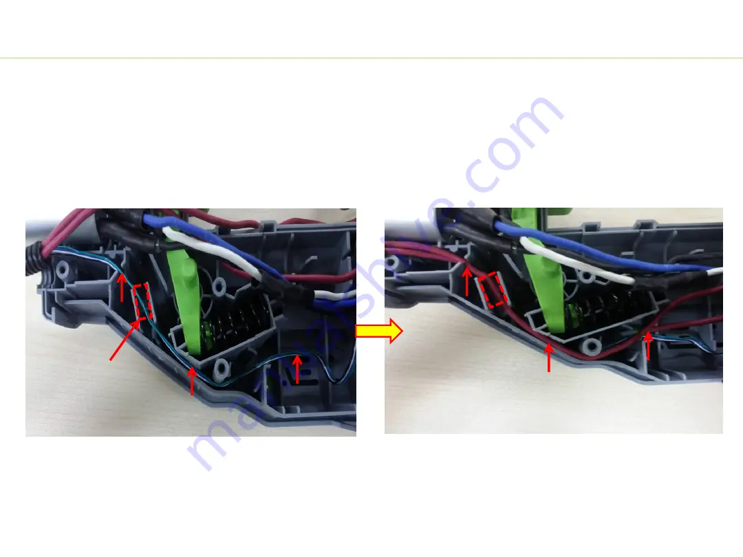
10. Place the wires in the housing grooves in sequence.
a) Align the thin cables (green, white and black) into the bottom of the housing groove through
channel 1.
b) Align the two red cables into the groove through channel 1.
BC1500E-F Bike Handle Line Trimmer
Summary of Contents for POWER BC1500E-F
Page 1: ...REPAIR GUIDELINE Bike Handle Line Trimmer _BC1500E F Version 1 Issue Data 12 02 2016...
Page 5: ...Part 1 Replacing the Connecting Tube 5...
Page 13: ...Part 2 Replacing the Motor Assembly 13...
Page 35: ...Part 3 Replacing the PCB Assembly 35...
Page 45: ...45 Replacing the PCB Assembly 13 Assemble the rear housing BC1500E F Bike Handle Line Trimmer...


