47
Replacing the PCB Assembly
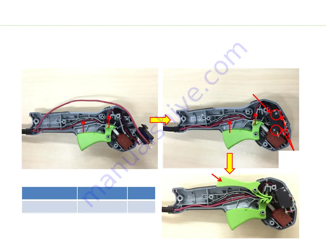
c) Place the interlock switch into the correct position aligning the two red cables one by one.
d) Place the interlock trigger into the right handle housing.
NOTICE:
if the switch trigger or interlock trigger is broken or worn, replace it with a new one.
Description
Part Number
Qty.
Interlock trigger
3128372001
1
Interlock Switch
Interlock trigger
Align holes
with poles
BC1500E-F Bike Handle Line Trimmer
Summary of Contents for POWER BC1500E-F
Page 1: ...REPAIR GUIDELINE Bike Handle Line Trimmer _BC1500E F Version 1 Issue Data 12 02 2016...
Page 5: ...Part 1 Replacing the Connecting Tube 5...
Page 13: ...Part 2 Replacing the Motor Assembly 13...
Page 35: ...Part 3 Replacing the PCB Assembly 35...
Page 45: ...45 Replacing the PCB Assembly 13 Assemble the rear housing BC1500E F Bike Handle Line Trimmer...


