EGS Electrical Group • www.appletonelec.com • 800-621-1506
330087 Rev. G 10/16
Page 3
P
owertite®
200 A
mP
P
in
& S
leeve
r
ecePtAcleS
: nemA 4X.
600 v
olt
Ac, 250 v
olt
dc. w
ire
r
eceSS
d
iAmeter
: .687”. w
ire
S
ize
rAnge
: 250mcm - 4/0
And
3/0 - #4.
P
owertite®
200 A
mP
P
in
& S
leeve
c
onnector
: nemA 4X.
250 v
olt
dc, 600 v
olt
Ac. w
ire
r
eceSS
d
iAmeter
: .687”. w
ire
S
ize
rAnge
: 250mcm - 4/0
And
3/0 - #4.
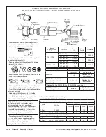
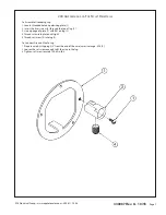
1. Remove the rear polarizing ring (1). Slide out the terminal block (2).
2. Follow paragraphs No. 2 and No. 5 for the plugs.
3. After wiring, slide terminal block assembly (2) in the back of housing (3). Replace the polarizing ring (1).
4. Tighten the angle adapter mounting bolts (4) to 50 to 70 in.-lbs. torque.
5. Tighten the receptacle mounting bolts (5) to 120 to 150 in.-lbs. torque.
1. Disassemble, as shown by loosening setscrews (1) and (2),
unscrew clamp cap (4) and housing cap (9), remove polarizing
plate (8), flat head screw (12) and terminal block assembly (10).
2. Follow instructions shown on paragraphs No. 2 and No. 3 for the
plugs.
3. Slide clamp cap (4), steel ring (7), proper grommet (6), housing
cap (9) and polarizing plate (8) over the cable.
4. Follow instructions shown on paragraph No. 5 for the plugs.
5. Slide terminal block assembly (10) into the housing (11) aligning
the hole in the ground bar with hole in the housing, Put in flat head
screw (12), tighten securely and put in polarizing plate (8).
6. Tighten housing cap (9) on the housing (11) and tighten
setscrew (1) securely.
7. Place the grommet (6) and steel ring (7) on the back of housing
cap (9), tighten the clamp cap (4) until the grommet (6) is tightened
around the cable and tighten the setscrew (2) and cable clamps (5)
securely.
Ground Male
Terminal Assembly
(Style 2 only)
Rear Polarizing
Ring (1)
Ground
Screw
Terminal Block
Assy (2)
Housing (3)
AJA
Mounting Box
Receptacle
Only*
Terminal Block
Assy (10)
Grommet (6)
Housing Cap (9)
Clamp Cap (4)
Style 1 (only)
Ground Wire
Assembly
Style 2
Ground Screw
Ground Male
Terminal Assembly
Flat Head
Screw (12)
Housing (11)
Cable
Clamps (5)
Set Screw (2)
Steel
Ring (7)
Set Screw (1)
Polarizing Plate (8)
Complete
Connector
Connector
Body Only


