9.
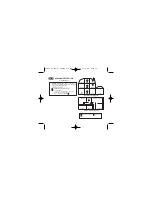
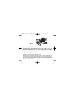
Connect the mains power to the alarm circuit. Check the green light on the front of
the alarm is on.
10.
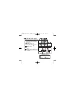
Attach the
‘Smoke Alarm’
identification label provided to the distribution board to
identify the alarm circuit.
11.
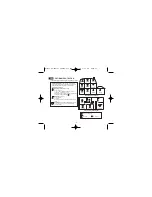
Attach the
‘Mains Smoke / Heat Alarms’
label provided on or near the distribution
board and write in date installed and the number of alarms on the circuit.
Ensure the alarm operates correctly - see “
TESTING & MAINTAINING YOUR
ALARM
” section on page 8 of the
USER INSTRUCTIONS
.
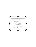
5.2 Interconnecting Alarms
Note:
A maximum of twelve Ei2110 Multi-Sensor Fire Alarms and/or Ei164RC Heat
Alarms may be interconnected along with an Ei128R/Ei128RBU relay (see
“
ACCESSORIES
” section on page 25). (Note the Multi-Sensor Fire Alarm Ei2110 can
also be interconnected to Ei141/144/146/161RC/166RC Smoke/Heat Alarms if
required). It can also be interconnected to Ei261ENRC/261DENRC Carbon Monoxide
Alarms provided an Ei1529RC Remote Control Switch is incorporated in the system -
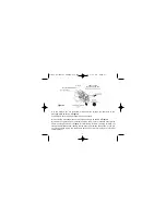
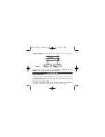
see page 25. Make electrical connections as shown in Figure 6.
If you wish to connect more than twelve alarms contact your local distributor (see page
28 for details).
Systems using more than 3 or 4 alarms must be very carefully planned to ensure
nuisance alarms are not excessive. e.g. from cooking fumes or steam. The following is
suggested:
• A Remote Control Switch (model Ei1529RC) should be incorporated into the system
23
B16350-R0-Ei2100 SERIES-U&C.qxd 18/9/08 3:46 PM Page 23

