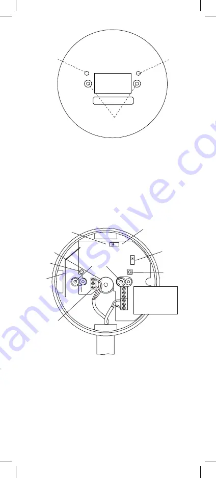
5. Connect the house wires (L-Live to wires coloured brown,
red or marked L, N-Neutral to wires coloured blue, black or
marked N) to the terminal block as shown in figure 1b.
NB: The unit must not be earthed so do not connect a green
/ yellow or copper earth wire to any terminal.
6. Connect the wires to the required relay contacts for controlling
the auxiliary device. (The contacts are isolated and are rated
at 250VAC, 5 amps resistive).
If momentary relay operation is required, carefully and
gently slide the yellow switch to the “P” position with a small
screwdriver (see figure 1b). This is commonly used with
warden call systems where only momentary short circuit
signalling is required. This must be done before the mains
power is connected or the rechargeable cells are activated.
With the switch in the “C” position, the alarm signal will
switch the latching relay until it receives a cancel signal.
7. Connect the rechargeable cells by carefully and gently sliding
the switch to the “ON” position (see figure 1b). This switch
must be in the ‘on’ position to ensure correct operation.
2
HOUSE
CODE
SWITCH
INDICATOR LIGHT
GREEN - MAINS
RED - LOW BATTERY
RED - HOUSE CODING
COVER ATTACHMENT
SCREWS
Figure 1a
RECHARGEABLE
CELLS
ON/OFF
SLIDE SWITCH
HOUSE CODE
SWITCH
C - CONTINUOUS RELAY
RELAY CHANGES
FOR 5 SECONDS
P - PULSE
ANTENNA
(KEEP CABLES
AWAY)
REAR ENTRY
KNOCKOUT
INDICATOR
LIGHT
CONNECT RELAY
WIRES TO THE
TERMINAL BLOCK
NO - NORMALLY OPEN
NC - NORMALLY CLOSED
C - COMMON
(DOUBLE INSULATE ALL WIRES)
SURFACE
CONDUIT
CABLE
ENTRY
SCREW
MOUNTING
HOLES
ON
OFF
NO
N
IC
L
L
IC
N
NC
C
CONNECT MAINS
TO TERMINAL BLOCK
L - LIVE
N - NEUTRAL
P
C
Figure 1b


