22
Phone:(910) 392
‐
2490
Fax: (910) 392
‐
2123
416 Landmark Drive
Wilmington, NC 28412
www.easterninstruments.com
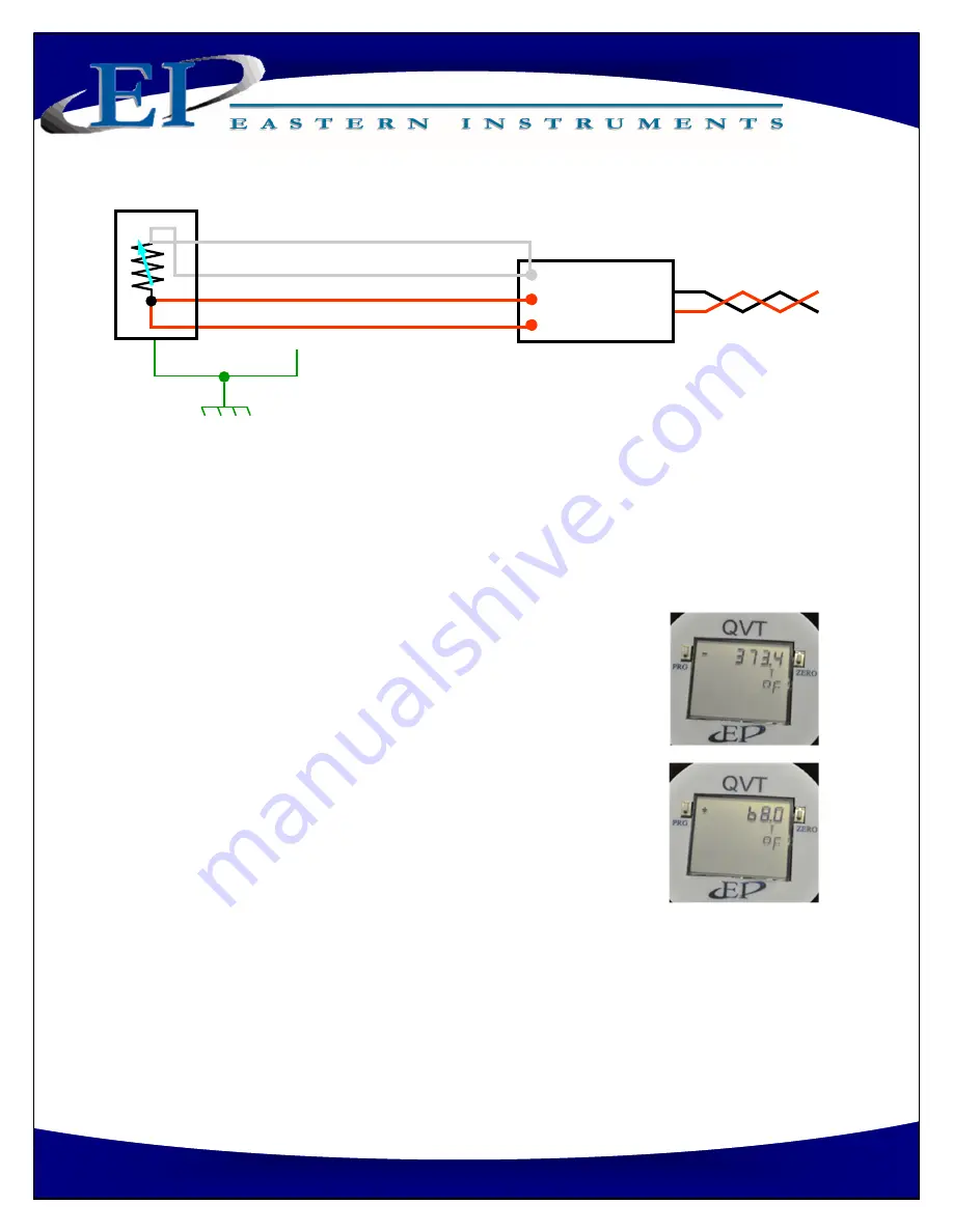
QVT
Transmi er
+
‐
White
Red
Red
Non
‐
Isolated RTD Input
Insulated RTD in head
Note: RTD wire colors
‐
EI uses the IEC standard of Red, Red, White where the
Red wires are common. Many other standards exist, but the common wires
are always the same color.
TYPICAL 4
‐
WIRE RTD INSTALLATION DIAGRAM
NOTE ON TEMPERATURE READINGS
: When the external RTD input temperature reading is out
of range (not between
‐
355°F[
‐
215°C] and +1589°F [865°C]) , due to a break, short or some
other condi on, then the QVT will revert to its sta c "Entered" value for Temperature for use
in its mass
fl
ow calcula on.
When this occurrence happens, the temperature display will alter
‐
nate between the RTD’s “fault” display (Image #1) and the
“Entered” Temperature value that will be used to calculate the mass
fl
ow for the 4
‐
20 mA output (Image #2). When the RTD has faulted
and the “Entered” Temperature value is being used, the Tempera
‐
ture Icon “T” will
fl
ash when displaying the “Entered” value. This is
an indica on that the “Entered” value is being used to calculate
mass
fl
ow rather than the RTD’s measured value.
Even a er the fault has been corrected and the RTD is reading the
Temperature correctly again, the QVT will con nue using the
“Entered” value for Temperature un l the QVT has been rebooted
(power removed and then restored). Once power has been cycled,
the QVT will begin using the RTD’s measured Temperature for its
mass
fl
ow calcula on and 4
‐
20 mA output.
As an indica on, the display will stop alterna ng between the meas
‐
ured Temperature and the stored or “Entered” value and the Tem
‐
perature Icon “T” will stop
fl
ashing.
#1
#2


