FUNZIONAMENTO
I
44
OPERATION
GB
44
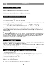
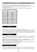
Aspira is equipped with touch sensitive electronic sensor keys.
Switch on the cooktop firstly, and then the desired cooking zone.
Press the power button
for at least 2 seconds.
All of the displays will light up. If no other inputs are provided, after a few seconds the cooktop will
automatically shut itself off for safety reasons.
Touch the key button for the desired cooking zone.
The display will show “0”; press + or – to select the desired power setting, ranging from 1 to P it is
possible to activate plate warmer mode indicated by the symbol U by selecting the power level
between 0 and 1
P:
indicates the
Booster
function, and is present on each of the cooking zones. To activate it,
press the + key to get to power setting 9, then press the key once more. This function will remain
active for 5 minutes, after which the system will reset itself to power setting 9. This function is
recommended to bring water to the boil more quickly.
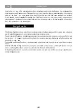
If no pots or receptacles are placed or recognised on the various cooking zones, the pot detection
function will indicate this condition with the symbol “u”.
Set a pot or pan of a suitable diameter and material onto the cooking zones, as described in the
section on suitable cooking containers.
The cooking zone will switch off automatically after 10 minutes if no pot is recognised.
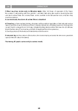
S
Touch the power button.
The main indicator light and cooking zone lights will switch off. The cooktop is now powered
off. The residual heat indicator, displayed as a H on each cooking zone, will remain lit until these
zones have not sufficiently cooled down.
Warning: risk of burns
Do not touch a cooking zone for which the indication (H) appears.
Switching on the cooktop
Activating the desired cooking zones
Pot Detection
Switching off the cooktop and residual heat indication
Summary of Contents for 5803
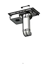
Page 2: ...2 ...
Page 4: ...r 5 800 515 474 759 220 214 173 4 ...
Page 5: ...5 600 480 222 50 300 100 c c ...
Page 6: ...6 480 760 r 5 5 5 50 760 804 2 0 2 0 519 480 2 0 2 2 MAX r5 r5 B B sez B B ...
Page 7: ... 7 ...
Page 8: ... 8 ...
Page 9: ... 9 ...
Page 10: ... 10 ...
Page 11: ... 11 ...
Page 12: ... 12 ...
Page 13: ... 13 ...
Page 14: ... 14 ...
Page 15: ... 15 ...
Page 16: ... 16 ...
Page 17: ... 17 ...
Page 18: ...18 ...
Page 19: ...19 ...
Page 20: ... 20 ...
Page 21: ... 21 ...
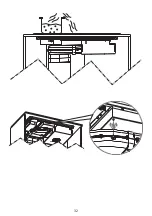
Page 22: ... 22 ...
Page 23: ... 23 ...
Page 24: ... 24 ...
Page 25: ... 25 ...
Page 26: ...26 ...
Page 27: ... 27 ...
Page 28: ... 28 ...
Page 29: ... 29 ...
Page 30: ... 30 ...
Page 31: ...31 ...
Page 32: ...32 ...
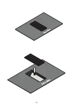
Page 33: ...33 ...
Page 34: ...34 ...
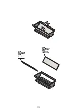
Page 35: ... 35 ...
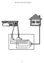
Page 36: ...36 Electrical connection diagram ...
Page 103: ...103 ...
Page 104: ...AFLIASPCB4OB01 Ed 16 04 20 ...


